Details on Cross Section
Information about the Cross section dialog in the pipeline corridor concept.
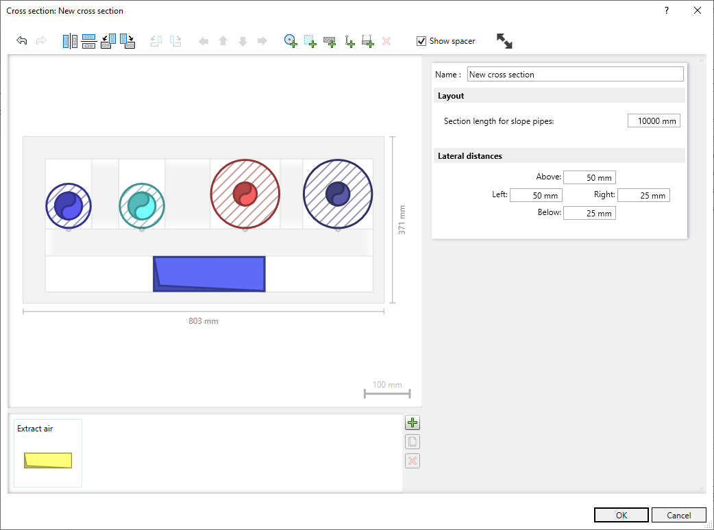
Different pipeline corridor sections in your project may have different pipeline corridor cross sections. In this dialog you can define new cross sections.
You are here:
Toolbar
| Symbol | Description |
|---|---|
| | Undoes changes or reverts the undone step. Alternatively, you can use the keyboard shortcuts Ctrl + Z and Ctrl + Y. |
| | Mirrors the entire configuration either around the vertical or horizontal axis. |
| | Rotates the entire configuration either counter-clockwise or clockwise. |
| | Rotates individual objects in the cross section either counterclockwise or clockwise. |
| | Moves the selected object in the configuration according to the selected arrow direction. |
| | Inserts a provision in the size of the selected pipe. |
| | Adds a reserved area to the cross section that does not contain any pipes and can be used as a plane for e.g. cross bonding. |
 | Adds a bracket profile to the cross section, which you can then move to the desired position. |
 | Adds a bracket thread to the cross section, which you can then move to the desired position. |
 | Adds a bracket construction consisting of two support threads and a support profile to the cross section. You can insert bracket constructions around the complete layout or around individual pipes/ducts. You can edit the individual objects of the support construction separately. |
| | Deletes the selected object. Alternatively, you can use the Del key. |
| Show spacer | Shows or hides lateral distances, spacers and anchors. |
| | Displays the entire configuration within the boundaries of the view range. |


Name (visible, when no pipes are selected): Name of the cross section.
Since different cross sections are assigned to different pipeline corridor sections, it is useful to take the location into account when assigning names, e.g. "EG_Nord_Wohnungen" for all pipeline corridor sections that come from the main pipe run and are supposed to supply individual apartments.
Layout
If no pipe is selected, the Layout section is displayed. The Section length for slope pipes indicates the length for which a given slope percentage is to be calculated.
Lateral distance
If no pipe is selected, the Lateral distance section is displayed. Here you can define minimum distances between the wall of the pipeline corridor and the pipe.
Distance holder
Click the line between adjacent pipes to activate the Distance holder section.
Distance: Enter the distance value in this field.
Clear distance: If you select this option, the value set under Distance will be set as the clear distance between the pipes.
Axis distance: If you select this option, the value set under Distance will be set as the distance between the pipes.
You can define a minimum distance between adjacent pipes in this section. If you change the value in the field Distance:, it will be used for all objects inserted into the cross section then. However, if you select a different distance holder in the cross section drawing, the underlying distance value is set for the subsequently inserted objects. This function allows you to easily repeat the dimensions of of the already existing distance holder for objects to be inserted.
You can copy existing distance holder with Ctrl + drag-and-drop and place them elsewhere in the layout. Depending on the setting of the neighboring pipes, the set distance refers to the outer edges or to the axes of the respective pipes.
If you are working with axes distances and the set distance would lead to collisions in the pipeline corridor construction, the area between the two distance points is colored red and the double arrow for indicating the distance is shortened. If the distance is so small that it cannot be selected with the mouse, you can navigate to the desired spacer in the layout using the arrow keys on the keyboard.
Pipe
If a pipe is selected, the Pipe section is displayed.
Name: Optional name for the selected pipe. The name can also be assigned to pipes stored in the pallet, e.g. to indicate the planned position of the pipe within the cross-section.
Discipline: Dropdown list to select the discipline for the selected pipe. Each discipline is displayed in the colors of the corresponding system classes.
System class: Drop-down list to select the system class within the selected discipline. Each system class is shown in its corresponding color. The pipes are displayed in the color of the selected system class.
Profile: A pipe profile can be selected for disciplines such as Ventilation.
Diameter, Width, Height: The dimensions of the pipe. Click  to open the Calculator, in which you can determine the required dimension from approximate input. For cable trays and air ducts, the width and height dimensions can be interchanged by clicking
  .
.
Insulation - activated: The input field for the thickness of the insulation becomes editable and the insulation thickness can be entered in absolute values or according to GEG.
Bracket
If a pipe/duct with a round profile is selected, the area Bracket is displayed.
Alignment: Drop-down list for selecting the direction in which the pipe/duct will be fixed. After selecting a direction, the pipe/duct is fixed with a bracket in the cross-section. Brackets always end at ceilings, floors, walls or bracket profiles.
Fixing elements are only used to take into account the space requirements of the fasteners in the path and are not generated when paths are generated.
Positioning
You can anchor a pipe or a reserved area within a cell to the sides. Any defined insulation is taken into account. Position anchors can also be created or deleted by double-clicking on the corresponding position of the pipe/reserved area.
If a pipe is outside the defined pipe corridor boundaries after the axis distance has been activated, the overhang is indicated by a white stripe. In such cases, either adjust the side distances of the pipe corridor or insert reserved areas as spacers.
Reserved area
If you select a reserved area, the Reserved area section is displayed.
Name: Optional name for the selected reserved area. If there are several reserved areas, the name can be used to distinguish them.
Width, Height: The dimensions of the reserved area can be specified in absolute values or in relation to the available space or the surrounding columns/rows. If the size is relative to surrounding columns/rows, the relevant pipes will be highlighted when the mouse is positioned over the corresponding drop-down list.
The options for Positioning are identical for pipes and reserved areas (see above).
Bracket profile
If you select a bracket profile, the Bracket profile section is displayed.
Alignment: Drop-down list to select the Alignment of the bracket profile.
Length, Thickness: Dimensions of the bracket profile. The option Stretch is set by default.
Stretch
Enabled: The length of the profile is stretched to the complete width or height of the layout, unless the profile collides with another element of the layout before.
Deactivated: The length of the profile is defined by the length specification in the Length input field.
Extension: Left, Right, Above, Below: Extends the bracket profile by a fixed value or up to the wall or floor or ceiling.
Triangular profile - enabled: A triangular profile is displayed in the cross section.
Brackets are only used to take into account the space requirements of the brackets in the path of the pipe corridor, they are not generated when pipe corridors are generated.
Threaded rod
If you have selected a threaded rod, the section Threaded rod is displayed.
Threaded rods for brackets are aligned horizontally or vertically depending on their positioning and are automatically stretched until they meet a wall, floor, ceiling or bracket profile to which they can be attached. The diameter of the threaded rod is preset to 10 mm and cannot be changed.
Fixing elements are only used to take into account the space requirements of the fasteners in the path and are not generated when paths are generated.
Palette
In the lower area of the cross section editor, click  to store pipes for placing them later. Pipes that have been added to a pipeline corridor via the LINEAR Properties dialog are also stored here. Pipes in the palette can be configured directly. Drag-and-drop the pipes to place them into the pipeline corridor configuration. You can also add pipes from the existing configuration to the palette by drag-and-drop.
 - duplicates the selected object.
 - deletes the selected object from the palette.