Cooling design with AutoCAD
With the LINEAR solutions, an integrated workflow in cooling design is guaranteed. From the first concept over the cooling load calculation, the product dimensioning and pipe network calculations up to a detailed 3D construction: Create your design quickly and efficiently with LINEAR on AutoCAD or CADinside.
The LINEAR workflow
Input:
Supply requirements for the building
Output:
Calculable scheme design
Work steps:
- Create storey table
- Manual scheme creation with toolbars and specific editing commands
- Scheme generator for drag and drop and automated drawing
Input:
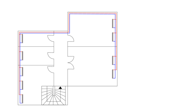
Architectural plan
Output:
Model for further MEP design including levels and rooms
Work steps:
- Referencing DWGs, DXFs or PDFs from the architect
- Create storey table
- Create and enrich the architecture with room data
Input:
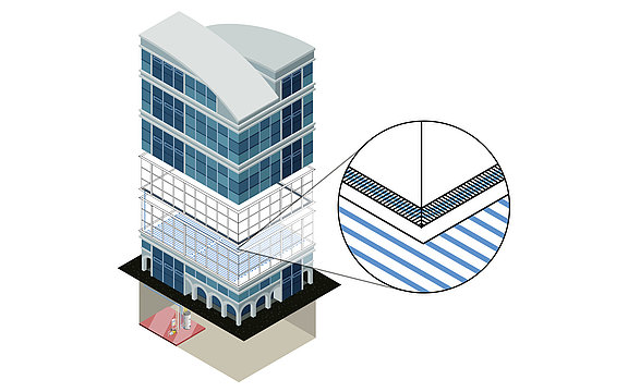
Architecture model with additional information for analysis
Output:
Calculated cooling load
Work steps:
- Powerful building analysis as a basis for the cooling load calculation
- Automatic mapping of the building structure (building parts, storeys and rooms)
- Identification and collaborative correction of modeling errors in exchange with the architect
- U-value calculation and addition of any missing calculation parameters
- Dynamic cooling load calculation for the project, the storeys as well as all rooms
- Transfer of all relevant values into the model
Input:
Calculated cooling load
Output:
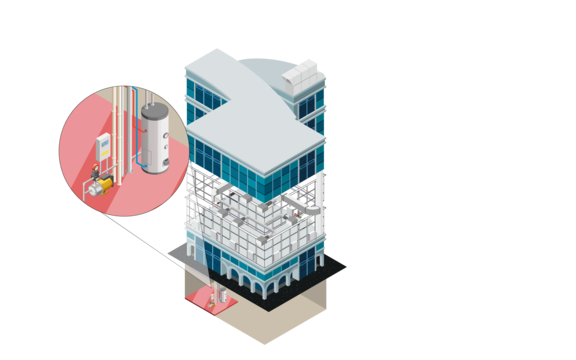
MEP model with dimensioned cooling components
Work steps:
- Dimensioning of convectors or panel cooling systems on the basis of the cooling load calculation
- Comparison of variants by using verified manufacturer data sets
- Transfer of the designed components into the model
- Optional automatic or manual placement of components
Input:
MEP model with dimensioned cooling components
Output:
MEP Model with a calculable network (isometric or floor plan)
Work steps:
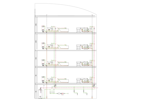
- 2D or isometric pipe network design using time-saving construction commands
- Automatic connection of all consumers
- System design in a neutral way or with the help of extensive manufacturer CAD libraries
Input:
MEP model with dimensioned cooling components
Output:
Detailed 3D model
Work steps:
- Detailed pipe design
- Automatic routing functions with preview of possible alternatives
- System design in a neutral way or with the help of extensive manufacturer CAD libraries
- Subsequent placement of components with matching transitions and flanges
- Automatic bolting of the entire construction (bolts, nuts, washers) with complete transfer to the parts list
- Pre-define insulation materials and show/hide them with transfer to the parts list
- Real-time collision check
- Manually or automatically assigned item numbers
- Material lists, parts lists with article numbers, sawing lists for pipes, position lists
Input:
Scheme, 2D or 3D model
Output:
MEP model with optimized cooling system (schematic, 2D or 3D)
Work steps:
- Specification of calculation-relevant specifications (e.g. assignment of pipe materials, settings of valves, specification of insulation and ambient temperatures).
- Comparison of variants by using verified manufacturer data sets (e.g. pipe systems)
- Calculation of existing networks by fixing individual or all dimensions
- Redimensioning of the heating pipe network based on the calculation
- Colored display of all results directly in the model
- Automatic 3D generation during system creation in 2D (step 5 - variant 1)
Input:
Calculated and optimized cooling pipe network
Output:
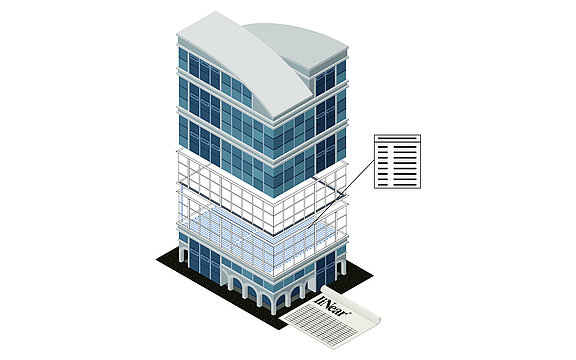
Final cooling design including model for transfer to the coordination model and calculation results incl. material lists
Work steps:
- Saving of all inputs and calculation results in the model
- Publication of selectable values as component data
- Automatic labeling of the model
- Addition of own parameters and meta information
- Printout of the results in standardized forms
- Transfer of results and model in all relevant formats
Input:
Supply requirements for the building
Output:
Calculable scheme design
Arbeitsschritte:
- Create storey table
- Manual scheme creation with toolbars and specific editing commands
- Scheme generator for drag and drop and automated drawing
Input:
Architectural plan
Output:
Model for further MEP design including levels and rooms
Arbeitsschritte:
- Referencing DWGs, DXFs or PDFs from the architect
- Create storey table
- Create and enrich the architecture with room data
Input:
Architecture model with additional information for analysis
Output:
Calculated cooling load
Arbeitsschritte:
- Powerful building analysis as a basis for the cooling load calculation
- Automatic mapping of the building structure (building parts, storeys and rooms)
- Identification and collaborative correction of modeling errors in exchange with the architect
- U-value calculation and addition of any missing calculation parameters
- Dynamic cooling load calculation for the project, the storeys as well as all rooms
- Transfer of all relevant values into the model
Input:
Calculated cooling load
Output:
MEP model with dimensioned cooling components
Arbeitsschritte:
- Dimensioning of convectors or panel cooling systems on the basis of the cooling load calculation
- Comparison of variants by using verified manufacturer data sets
- Transfer of the designed components into the model
- Optional automatic or manual placement of components
Input:
MEP model with dimensioned cooling components
Output:
MEP Model with a calculable network (isometric or floor plan)
Arbeitsschritte:
- 2D or isometric pipe network design using time-saving construction commands
- Automatic connection of all consumers
- System design in a neutral way or with the help of extensive manufacturer CAD libraries
Input:
MEP model with dimensioned cooling components
Output:
Detailed 3D model
Arbeitsschritte:
- Detailed pipe design
- Automatic routing functions with preview of possible alternatives
- System design in a neutral way or with the help of extensive manufacturer CAD libraries
- Subsequent placement of components with matching transitions and flanges
- Automatic bolting of the entire construction (bolts, nuts, washers) with complete transfer to the parts list
- Pre-define insulation materials and show/hide them with transfer to the parts list
- Real-time collision check
- Manually or automatically assigned item numbers
- Material lists, parts lists with article numbers, sawing lists for pipes, position lists
Input:
Scheme, 2D or 3D model
Output:
MEP model with optimized cooling system (schematic, 2D or 3D)
Arbeitsschritte:
- Specification of calculation-relevant specifications (e.g. assignment of pipe materials, settings of valves, specification of insulation and ambient temperatures).
- Comparison of variants by using verified manufacturer data sets (e.g. pipe systems)
- Calculation of existing networks by fixing individual or all dimensions
- Redimensioning of the heating pipe network based on the calculation
- Colored display of all results directly in the model
- Automatic 3D generation during system creation in 2D (step 5 - variant 1)
Input:
Calculated and optimized cooling pipe network
Output:
Final cooling design including model for transfer to the coordination model and calculation results incl. material lists
Arbeitsschritte:
- Saving of all inputs and calculation results in the model
- Publication of selectable values as component data
- Automatic labeling of the model
- Addition of own parameters and meta information
- Printout of the results in standardized forms
- Transfer of results and model in all relevant formats
Features
Construction tools
- Pipe routing including system class determination with automatic transfer of media and distances in all view types
- Automatic connection of pipes including necessary transitions (autorouting)
- Automatic T-piece connection
- Offset command for the resolution of collisions
- Symbols for heating, cooling, gas and architecture (freely expandable)
- Animated hydraulic assistant for the creation of hydraulic circuits
- 2D piping design & 2D manifold generator for detailed design
- Work on 2D and 3D documents: DWG, DXF, PDF, JPEG, PNG, etc. including design assistant for roof structures
- Void planning
- Parts lists with short and long texts
- Configurators for convectors, manifolds and tanks
- Routing command for construction of several pipes at once
- Panel cooling assistant for circular routing and connection
- Automatic labeling and legend generation
Scheme generator
Create the fastes schemes in the industry with the powerfull scheme generator
- Generate a complete and calculable scheme with drag and drop
- Creating schemes even without CAD experience
- Automatic drawing of scheme
- Define sections and bows
- Easy copy of storeys and pipe runs
- Definition of components (e.g. valves and pumps) already in the generator
- Saving and Importing of existing configurations
Dynamic cooling load calculation
- Automatic transfer of all building sections, storeys, rooms and room components directly from the Revit model
- Dynamic Cooling load calculations based on multiple national and international norms
- Calculation of the room air temperature
- Calculation of the operative room temperature
- Assistant for determination of internal and external loads
- Cross-project definition of reusable profiles (loads, brightness, usage, temperatures, operating profiles, etc.)
- Calculation by means of periodic settling with CDD or by means of aperiodic settling with CDP (defined forward run, start and CDD)
- Separate display of the results for dry (residual) cooling load, the cooling load from panel cooling, the cooling load from AHU/ supply air system and the total cooling load
- Window configurator with shadow consideration
- Parametric data model for easy changes
- Automatic update after changes in the architectural model
- Extensive material library for defining components
- Quick and easy calculation of U-values
- Faster input by creating standard components
Automatic drawing in of the layout
- Automatic placement of radiators, convectors and panel heating systems into your CAD model
- Automatic labeling of transferred components
- Transfer and update of dimensioned components into your model and from your model to the dimensioning
Dimensioning of the panel cooling systems
- Dimensioning and layout of panel cooling (floor, wall and Ceiling) based on the cooling load calculation
- Easy variant comparison
- Determination and assignment of pipe runs, manifolds, manifold connections and control components (e.g. valves)
- Automatic creation of pipe run schemes
- Extensive data sets of manufacturer products for radiators, convectors and panel heating systems
Dimensioning of cooling convectors
- Dimensiong of convectors for each room based on the head load calculation
- Consideration of allready integrated convectors in the model and new dimensioning, layout and update of the model
- Easy variant comparison
- Determination and assignment of pipe runs, manifolds, manifold connections and control components (e.g. valves)
- Extensive data sets of manufacturer products for convectors and panel cooling systems
Architecture creation for the calculations
- Creation of a 3D architectural model for building analysis based on multiple document formats such as DWG, DXF, PDF, PNG or JPEG.
- Simple tools for creating walls, windows, doors, roofs, etc.
- Optimized room detection through automatic room identification
- Automatic updating of floor plan changes
- Automatic transfer of building parts, floors, rooms, room components and temperatures into building analysis
Building analysis
- Building detection and analysis including the information required for load calculations (e.g. target heating and cooling temperatures)
- Definition and transfer of further building parameters (e.g. apartment names)
- Detection of storeys and rooms
- Automatic transfer of all building storeys, rooms and room components including room temperatures and adjacent temperatures directly from the AutoCAD model
Detailed 3D pipe network design
- Pipe design with routing function and pipe classes for creating the fittings with millimeter precision (integrated slope construction)
- Automatic connection of pipes including transfer of media, materials, dimensions and pressure levels.
- Manifold generator for the production of assemblies including pumps and valves and configurators for tanks, plate heat exchangers and other devices
- Insertion of components with suitable transitions and flanges in existing systems
- Real-time collision check
- Automatic 3D generation of calculated single-line drawings
- Connection editor for your own 3D components
- Automatic connection of pipes including transfer of media, materials, dimensions and pressure levels
- Automatic bolting of the entire construction (bolts, nuts, washers) with complete transfer to the parts list
- Predefine insulation materials and show or hide them with transfer to the parts list
- Consideration of deductions for welding seams, gaskets and insertion and bolting depths
- Manually or automatically assigned item numbers
- Material lists, parts lists with item numbers, sawing lists for pipes, item lists
Automatic detection of the pipe network
- Detection of drawn pipes directly in the model and analysis of the system
- Detection of all integrated components
- Consideration of technical datas integrated in the model
- Detection of drawn dimension for the optional consideration in the network calculation
- Easy mapping of foreign components for the consideration in the network calculation
Hydraulic balancing of complex systems
- Hydraulic calculations with transfer of performance data from family parameters
- Calculation of multiple systems in one model
- Calculation also of networks with several control levels
- Consideration not only of the distribution networks but also of the producer
Pipe network calculation with redimensioning
- Automatic calculation and dimensioning of all components in the pipe network
- Consideration of given gerneral conditions e.g. limit values for velocities and the pipe friction pressure gradient (R-value)
- Extensive adjustment possibilities for the calculation boundary conditions (maximum velocities, valve authorities, active pipe diameters, fixed pipe dimensions for existing systems, etc.)
- Determination and variant comparison of pipe materials and components including original manufacturer data sets with real product properties
- Calculation directly in the model incl. redimensioning
- Hydraulic calculations with transfer of performance data from parameters
- Calculation of multiple systems in one model
- Selection of suitable (manufacturer) components based on the calculation results
- Saving of values directly in the model with optional consideration in the IFC export
- Interface for valve data sets, shut-off valves, differential pressure closed-loop controllers, volume flow closed-loop controllers, regulating valves, control valve and fixed resistors
- Visualization of results using liNear Data Coloring (dimensions, materials, velocities, unfavorable flow path and many more)
Industry components via CAD Browser
- Extensive CAD libraries with approved components of our wide range of industry partner
- More than 6 billion possible components and component combinations
- Direct placement of original manufacturer components into your model
- Multiple placing modes (place, insert, replace)
- Configurators for complex component combinations (e.g. cascade systems)
- Including technical and commercial data (e.g. article numbers and packaging units)
- Detection and consideration in the network calculations
Supported standards
LINEAR has always stood for standard-compliant calculation and design. It is both our concern to always offer the latest standards and to constantly expand the range nationally and internationally. An up-to-date overview of all supported standards can be found in our LINEAR Knowledge Base.
Parts list with article numbers
- Clear and comprehensible calculation results as well as complete bill of quantities
- Detailed parts lists including article numbers and material check
- Bill of quantities and parts lists in several output formats (Windows printout, Excel, text, UGS, GAEB, ASD)
Language selection for interface and printouts
We provide you with no less than seven languages, which you can use and combine as you wish, either as the interface language or the print language. In this way, it is possible to design in one language and print in another. This is a great advantage, especially for international projects, as time-consuming translations are no longer necessary. There are no additional costs for the language packages.
The following languages are currently supported:
- German
- English
- French
- Dutch
- Russian
- Turkish
- Italian
Visibility control
Visibility control with one click for:
- Building parts
- Floors
- Disciplines
- component groups (e.g. systems, insulation, etc.)
IFC interface
- IFC import of the architecture
- IFC export including all metadata
- Selection of the disciplines to be considered for the export
Storey table
- Automatic import of storeys from the architectural model
- Control of the storey in the Construction level / offset (+/-) section
- Easy Creation of storeys and work levels
FM-Tools
- Import and export of information for facility management
- Import of information from FM databases