Heating design for Revit
With the LINEAR solutions, a continuous workflow in heating design is guaranteed. From the design in early concept phases and the MEP model creation to the building analysis and heat load calculation to the product dimensioning and pipe network calculation: Create your design quickly and efficiently with LINEAR for Revit.
The LINEAR workflow
Input:
Concept structure of the architecture with rooms, floors and functional areas
Output:
Located space requirements for technical rooms and pipeline corridors
Work steps:
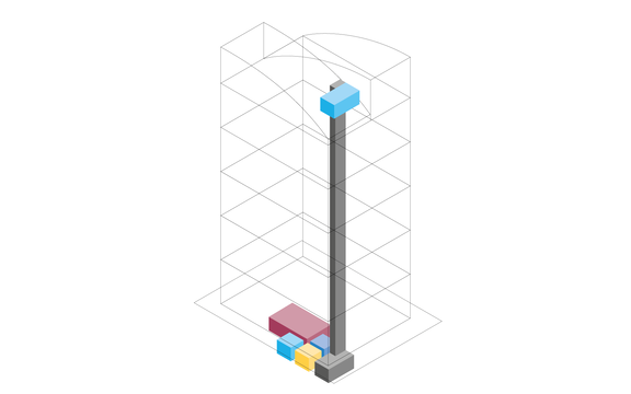
- Workflow for a collaborative early design phase planning
- Creation of a concept design on the basis of the requirements planning
- Conceptual space design (Provision for spaces)
- Localization and pre-dimensioning of technical equipment rooms
- Localization and pre-dimensioning of the pipeline corridors
- Cross section editor for the pipeline corridor concept
- Generate pipe and duct elements from corridor concept
Input:
Architecture model or plan
Output:
Model for further MEP design including levels, zones & MEP rooms
Work steps:
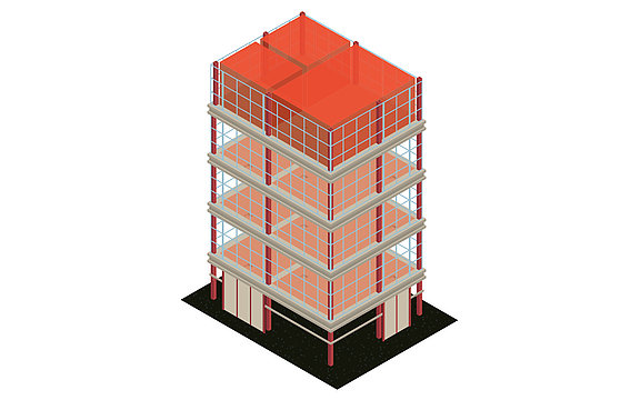
- Transfer of all relevant floor levels
- Automatic creation of views and plans
- Zoning and creation of MEP rooms
- Enrichment of the model with relevant information
- Parameter management for the assignment of parameters used in the project
- Optional for 2D templates: Simple rebuild of the building in 3D
Input:
Model for the MEP design including levels, zones & MEP rooms
Output:
Calculated heat load
Work steps:
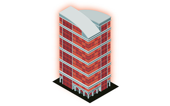
- Powerful building analysis as basis for heating load calculation
- Optional analysis of the terrain topography
- Automatic mapping of building structure (building parts, floor and rooms)
- Identification and collaborative correction of modeling errors in exchange with the architect
- U-value calculation and addition of any missing calculation parameters
- Automatic heat load calculation for the project, the floors as well as all rooms
- Transfer of all relevant values into the model
Input:
Calculated heat load
Output:
MEP model with dimensioned heating components
Work steps:
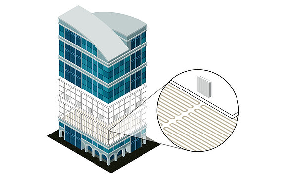
- Dimensioning of radiators, convectors or panel heating systems on the basis of the heat load calculation
- Comparison of variants by using verified manufacturer data sets
- Transfer of the dimensioned components into the model
- Optional automatic or manual placement of components
- Bidirectional adjustments either in the model or in the dimensioning
- Transfer of all relevant values into the model
Input:
MEP model with dimensioned heating components
Output:
MEP model with optimized systems as well as the finished void planning
Work steps:
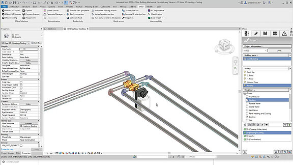
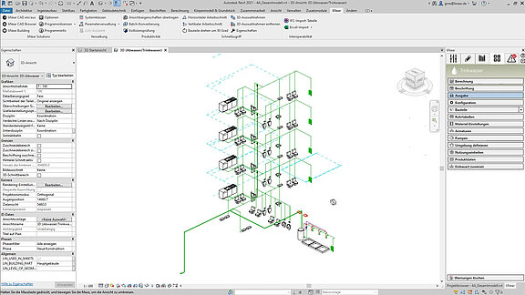
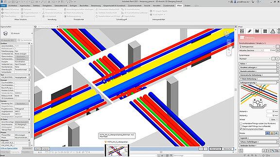
- Fast pipe network construction as a single pipe or as parallel pipes
- Automatic connection of all consumers
- Plant design neutral or with the help of extensive manufacturer CAD libraries
- Specification of calculation-relevant specifications (e.g. assignment of pipe materials, settings of valves, specification of insulation and ambient temperatures)
- Comparison of variants by using verified manufacturer data sets (e.g. pipe systems)
- Calculation of existing networks by fixing individual or all dimensions
- Redimensioning of the heating pipe network on the basis of the calculation
- Colored display of all results directly in the model (LINEAR data coloring)
- Void planning including coordination via BCF and IFC
Input:
Calculated and optimized heating pipe network
Output:
Final heating design including model for transfer to the coordination model and calculated results incl. material lists
Work steps:
- Storage of all inputs and calculation results in the model
- Publication of selectable values as shared parameters
- Automatic labeling of the model
- Addition of own parameters and meta information
- Printout of the results in standardized forms
- Transfer of the results and the model in all relevant formats
Input:
Concept structure of the architecture with rooms, floors and functional areas
Output:
Located space requirements for technical rooms and pipeline corridors
Arbeitsschritte:
- Workflow for a collaborative early design phase planning
- Creation of a concept design on the basis of the requirements planning
- Conceptual space design (Provision for spaces)
- Localization and pre-dimensioning of technical equipment rooms
- Localization and pre-dimensioning of the pipeline corridors
- Cross section editor for the pipeline corridor concept
- Generate pipe and duct elements from corridor concept
Input:
Architecture model or plan
Output:
Model for further MEP design including levels, zones & MEP rooms
Arbeitsschritte:
- Transfer of all relevant floor levels
- Automatic creation of views and plans
- Zoning and creation of MEP rooms
- Enrichment of the model with relevant information
- Parameter management for the assignment of parameters used in the project
- Optional for 2D templates: Simple rebuild of the building in 3D
Input:
Model for the MEP design including levels, zones & MEP rooms
Output:
Calculated heat load
Arbeitsschritte:
- Powerful building analysis as basis for heating load calculation
- Optional analysis of the terrain topography
- Automatic mapping of building structure (building parts, floor and rooms)
- Identification and collaborative correction of modeling errors in exchange with the architect
- U-value calculation and addition of any missing calculation parameters
- Automatic heat load calculation for the project, the floors as well as all rooms
- Transfer of all relevant values into the model
Input:
Calculated heat load
Output:
MEP model with dimensioned heating components
Arbeitsschritte:
- Dimensioning of radiators, convectors or panel heating systems on the basis of the heat load calculation
- Comparison of variants by using verified manufacturer data sets
- Transfer of the dimensioned components into the model
- Optional automatic or manual placement of components
- Bidirectional adjustments either in the model or in the dimensioning
- Transfer of all relevant values into the model
Input:
MEP model with dimensioned heating components
Output:
MEP model with optimized systems as well as the finished void planning
Arbeitsschritte:
- Fast pipe network construction as a single pipe or as parallel pipes
- Automatic connection of all consumers
- Plant design neutral or with the help of extensive manufacturer CAD libraries
- Specification of calculation-relevant specifications (e.g. assignment of pipe materials, settings of valves, specification of insulation and ambient temperatures)
- Comparison of variants by using verified manufacturer data sets (e.g. pipe systems)
- Calculation of existing networks by fixing individual or all dimensions
- Redimensioning of the heating pipe network on the basis of the calculation
- Colored display of all results directly in the model (LINEAR data coloring)
- Void planning including coordination via BCF and IFC
Input:
Calculated and optimized heating pipe network
Output:
Final heating design including model for transfer to the coordination model and calculated results incl. material lists
Arbeitsschritte:
- Storage of all inputs and calculation results in the model
- Publication of selectable values as shared parameters
- Automatic labeling of the model
- Addition of own parameters and meta information
- Printout of the results in standardized forms
- Transfer of the results and the model in all relevant formats
Features
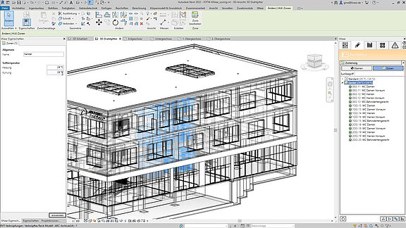
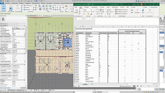
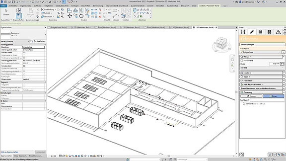
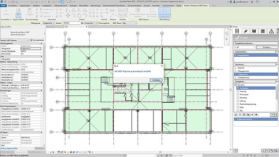
MEP model creation (Architecture)
- Automatic or manual MEP room creation
- Zoning tool
- Architectural functions for easy post-modeling of 2D architectural plans
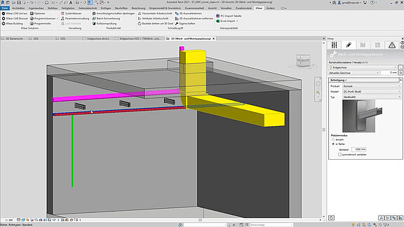
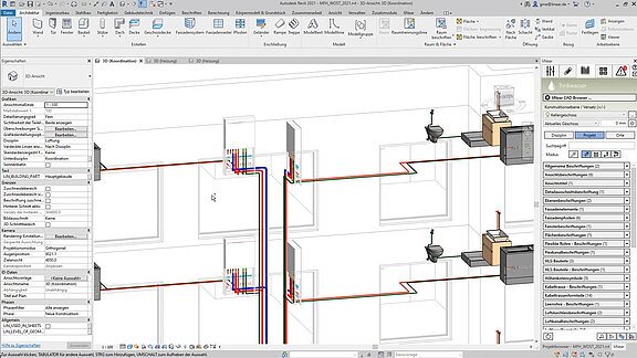
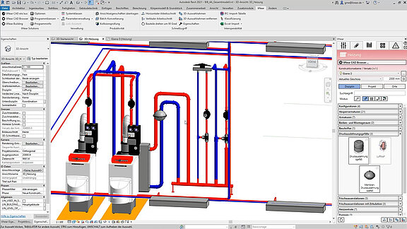
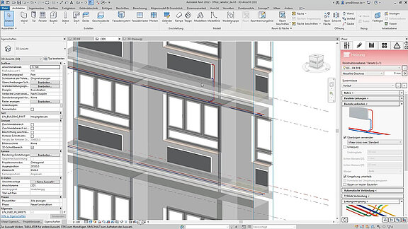
Construction tools
- Piping command including system class determination
- Automatic connection of pipes, including necessary transitions (autorouting)
- Automatic T-piece connection
- Offset command for resolving collisions
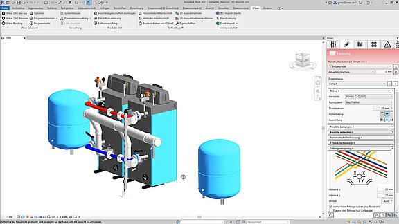
- Configurators for radiator, convector, manifolds and tanks
- Construction of parallel lines
- Design of panel heating also with circular objects
- Design tools for fixings, flanges, delivery lengths, etc.
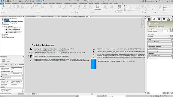
- Legend function
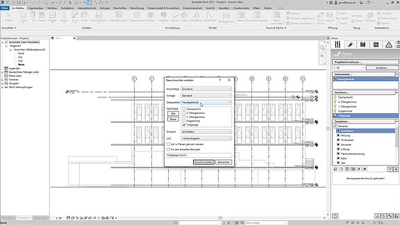
View creator and view control
- View creation assistant for 3D views, floor plans, ceiling plans and area plans
- Quick 3D selection box command
- Quick working section commands
- Automatic sorting and assignment of views
- Suggestions for best suitable views
- Automatic LOG assignement to views
- View filter
Storey table
- Automatic import of storeys from the architectural model
- Control of the storey in the Construction level / offset (+/-) section
- Easy Creation of storeys and work levels
- Separate storey table for mutliple building parts (e.g. for split levels)
Collaboration in early design phases
- Workflow for a collaborative early design phase planning
- Dimensioning of equipment rooms
- Conceptual space design (Provision for spaces)
- Cross section editor for the pipeline corridor concept
- Redimensioning of provisions for space
- Generate pipe and duct elements from corridor concept
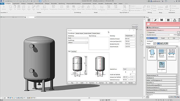
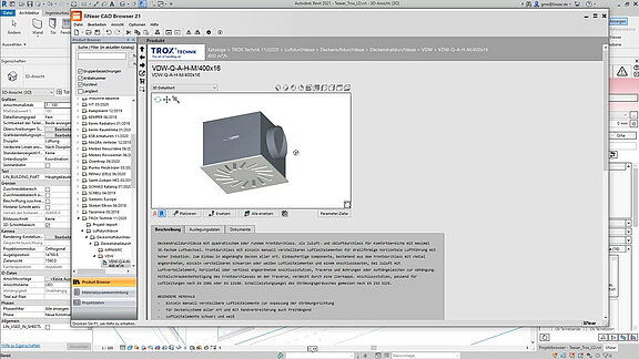
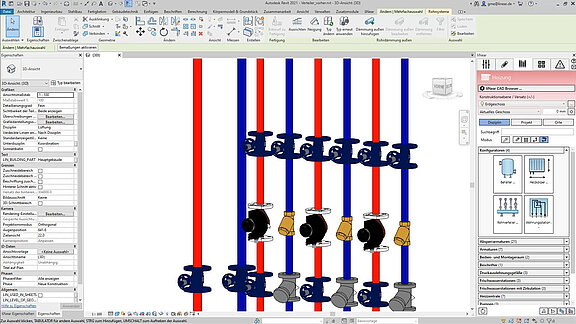
Industry components via CAD Browser
- Extensive CAD libraries with approved components of our wide range of industry partner
- More than 6 billion possible components and component combinations
- Direct placement of original manufacturer components into your model
- Multiple placing modes (place, insert, replace)
- Configurators for complex component combinations (e.g. cascade systems)
- Including technical and commercial data (e.g. article numbers and packaging units)
- Detection and consideration in the network calculations
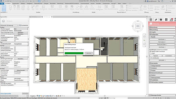
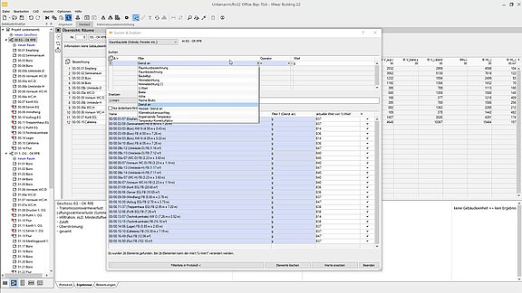
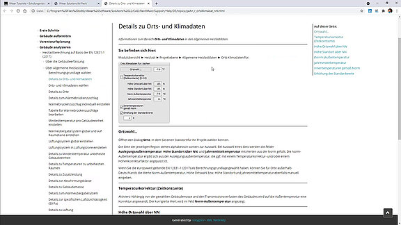
Building analysis
- Building detection and analysis including the information required for load calculations (e.g. target heating and cooling temperatures)
- Definition and transfer of further building parameters (e.g. apartment names)
- Detection of Building parts, storeys, zones and rooms
- Automatic transfer of all building sections, storeys, rooms and room components including room temperatures and adjacent temperatures directly from the Revit model
- Detection and consideration of ground approximation
- Automatic check of modeling mistakes in the architectural model to communicate to the architect
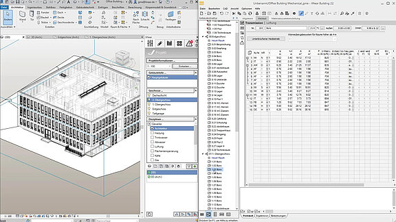
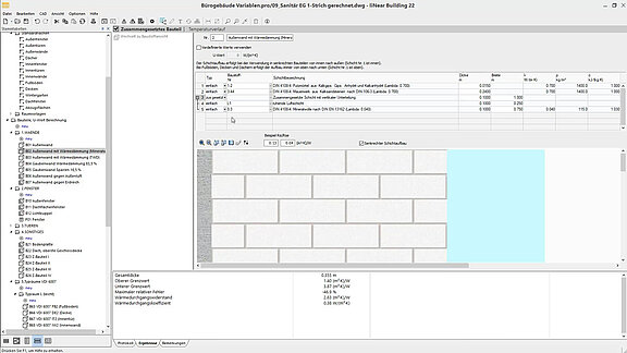
Heat load calculation
- Automatic transfer of all building sections, storeys, rooms and room components directly from the CAD model
- Heat load calculations based on multiple national and international standards
- Quick and easy calculation of U-values
- Parametric data model for easy changes
- Automatic update after changes in the architectural model
- Extensive material library for defining components
- Faster input by creating standard components
Automatic detection of the pipe network
- Detection of drawn pipes directly in the model and analysis of the system
- Detection of all integrated components
- Consideration of technical datas integrated in the model
- Detection of drawn dimension for the optional consideration in the network calculation
- Easy mapping of foreign components for the consideration in the network calculation
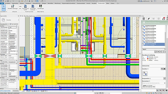
Pipe network calculation with redimensioning
- Automatic calculation and dimensioning of all components in the pipe network
- Consideration of given gerneral conditions e.g. limit values for velocities and the pipe friction pressure gradient (R-value)
- Extensive adjustment possibilities for the calculation boundary conditions (maximum velocities, valve authorities, active pipe diameters, fixed pipe dimensions for existing systems, etc.)
- Determination and variant comparison of pipe materials and components including original manufacturer data sets with real product properties
- Calculation directly in the model incl. redimensioning
- Hydraulic calculations with transfer of performance data from family parameters
- Calculation of multiple systems in one model
- Selection of suitable (manufacturer) components based on the calculation results
- Saving of values directly in the model with optional consideration in the IFC export
- Interface for valve data sets, shut-off valves, differential pressure closed-loop controllers, volume flow closed-loop controllers, regulating valves, control valve and fixed resistors
- Visualization of results using liNear Data Coloring (dimensions, materials, velocities, unfavorable flow path and many more)
Hydraulic balancing of complex systems
- Hydraulic calculations with transfer of performance data from family parameters
- Calculation of multiple systems in one model
- Determination also of networks with several control levels
- Consideration not onlyof the distribution networks, but also the generator part
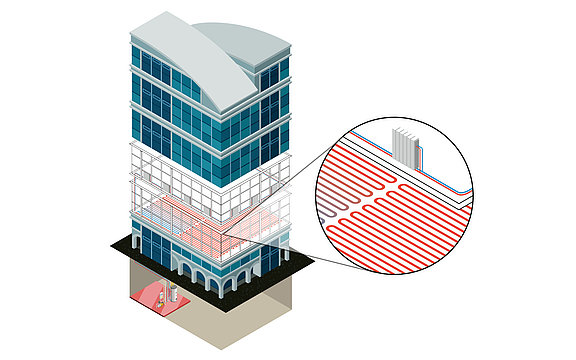
Dimensioning of panel heating
- Dimensioning and layout of panel heating (floor, wall and Ceiling) based on the heat load calculation
- Easy variant comparison
- Determination and assignment of pipe runs, manifolds, manifold connections and control components (e.g. valves)
- Automatic creation of pipe run schemes
- Extensive data sets of manufacturer products for radiators, convectors and panel heating systems
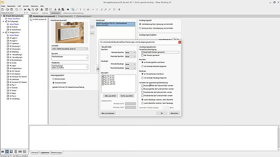
Dimensioning of radiators & convectors
- Dimensiong of radiators and/or convectors for each room based on the heat load calculation
- Consideration of allready integrated radiators in the model and new dimensioning, layout and update of the model
- Easy variant comparison
- Dimensioning for two and one pipe systems
- Determination and assignment of pipe runs, manifolds, manifold connections and control components (e.g. valves)
- Extensive data sets of manufacturer products for radiators, convectors and panel heating systems
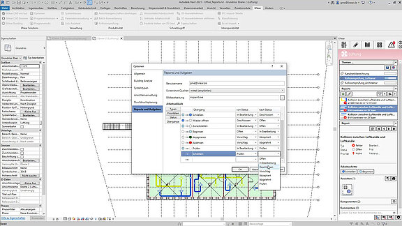
Task management
- Assigning of responsibilities for automatic (e.g. from the calculations) or manually created tasks
- Set of deadlines and priorities for tasks
- Status tracking of tasks
- Definition of given workflows for the resolution of tasks
- Adding of Screenshots, comments, positions to tasks
- Sharing and assignment of tasks to participants via BCF
Automatic labeling
- Automatic label-selection according to the component class
- Free configuration of label content
- Addition of custom parameters and meta information
- Automatic dimensioning
Family and library management
- Providing of all necessary components for your project centrally
- Components or configurators suitable for the active discipline
- Filtered by active discipline, used in project and locations (local or folder in the network)
- Sorted in component groups for quick orientation
- Multiple placing comands for families (place, replace, replace all, place on grid)
- Integration of own family libraries
- Intelligent search function
- Pick and place again of a component in the model
Interoperability and collaboration
- IFC Import configuration
- Classification of IFC or other structures
- Excel import and export
- Reports and tasks manager for BCF exchange (incl. chat function)
- Common topics and status tracking for BCF exchange
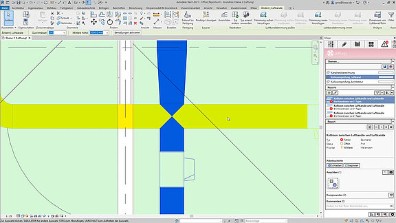
Collision checker
- Detection and display of collisions of any kind within a project or between several projects
- Collision check between Architecture and all disciplines
- Collision check between two discipline or one discipline with the architecture
- Collision check between single or multiple categories (e.g. walls and pipes)
- Collision check between single or multiple systems (e.g. Gas and exhaust air)
- Automatic creation of tasks for each collision in the Report and Task Tab
- Saving and Loading of predefined configurations
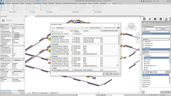
Parameter manager and classification tool
- Assigning of liNear parameters to your own shared parameters in a project-dependent mapping table
- Search and filter functions for mapping or overwrite of parameters
- Loading and Saving of predefined project standards
- Assignment of classification parameter to components and model elements to fill it with values
- Structure the classification of component groups in the IFC export
- Classification components related to cost groups for precise cost estimations
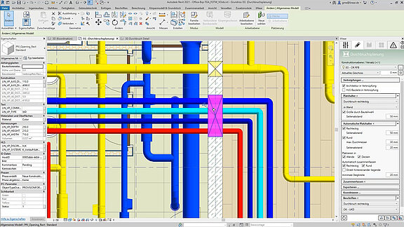
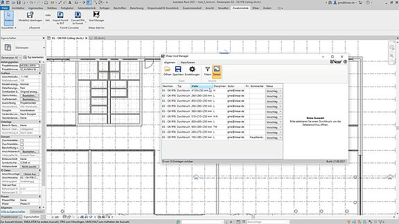
Void planning
- Manual placement
- Automatic placement
- Across referenced files
- BCF-Export (optional incl. IFC) for collaboration
- BCF-import for status alignment
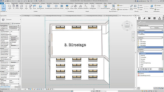
Visibility control
- One click visibility control for building parts
- One click visibility control for storeys
- One click visibility control for disciplines
- One click visibility control for component groups (e.g. systems, insulations, etc.)
Language selection for interface and printouts
We provide you with no less than seven languages, which you can use and combine as you wish, either as the interface language or the print language. In this way, it is possible to design in one language and print in another. This is a great advantage, especially for international projects, as time-consuming translations are no longer necessary. There are no additional costs for the language packages.
The following languages are currently supported:
- German
- English
- French
- Dutch
- Russian
- Turkish
- Italian
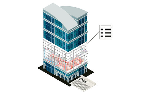
Parts list with article numbers
- Clear and comprehensible calculation results as well as complete bills of materials
- Detailed parts lists with part numbers and material checks
- Bills of materials in various output formats (Windows printout, Excel, text, UGS, GAEB, ASD)
Management of system class properties and quick selection
- Central management of system class properties
- Intuitive system table
- Quick selection of the system
Supported standards
LINEAR has always stood for standard-compliant calculation and design. It is both our concern to always offer the latest standards and to constantly expand the range nationally and internationally. An up-to-date overview of all supported standards can be found in our LINEAR Knowledge Base.
Feature videos

Feature videos