Details on Room view
Information on the Room view in panel heating/cooling.
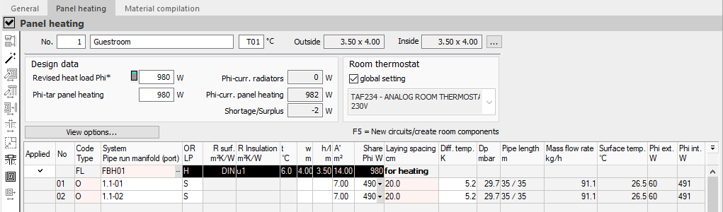
In the room view you can design, control and adjust the exact layout of a selected room.
You are here:
Room view
The room number, the room name and the room temperature are displayed. The specifications can be adjust here. The Exterior and Interior fields show the exterior or interior clear dimensions of the room. An adjustment of the dimensions can be carried out in the Room data dialog.
 : Opens the dialog Room data, which allows to adjust the parameter of the room.
Design data
Revised load Phi*
Indicates the revised heating or cooling load of the room. The value can be adjusted here.
 : Opens the dialog Approximate heat loador Approximate cooling load, in which the approximate load can be calculated based on the room area.
Phi-current radiator, Phi -current other
The display field shows the capacity of existing radiators in case of panel heating, and the capacity of other cooling systems of the room in case of panel cooling.
Phi-target panel heating/cooling
Indicates the required heat or cooling load of the room. If you would like to take the room’s radiators or cooling convectors into account for the calculation, this value may differ from Phi*. The value can be adjusted here.
Phi-actual panel heating/cooling
The display field shows the capacity of all panel heating or cooling systems existing in the room.
Shortage/Surplus
The display field shows the shortage or surplus of the heat or cooling load of the room.
Room thermostat
Global setting
Activated: The room is assigned to the globally defined room thermostat, which is shown in the field below. If no controller is displayed in the field, no global control has been defined yet or an single room control system has been selected that does not include a room thermostat. Control components are defined in the Control area, which can be called up in the Pipe run view.
Deactivated: The definition of the room is not done after the global setting and it can be opened with the button  the Select a single room closed-loop control system dialog. In this dialog, an individual control can be assigned to the room. The selection of the components of the dialog depends on the manufacturer or system.
View options...
View options...: Opens the context menu to define the displayed elements in the table of room components. The following Views are possible.
-
Show used room components only
Displays only room components that are assigned with panel systems.
-
Show detailed circle connections
Displays the data of the entire supply line and the corresponding distributor of the circuits.
Tip:Supply lines laying in other rooms are also displayed. This saves you from having to switch to the pipe run view.
Table of room components
The individual table columns of the component entry are explained below. During dimensioning, two different elements are created in the table: The component covered with the selected panel system (floor, ceiling or wall) and the heating or cooling circuit itself (as an occupied zone, border, feed pipe zone or blind area). Which element is available is indicated by the entry in the table column Code Typeto recognize.
| Column | Description |
|---|---|
| Applied | Used Indicates whether a room component is designed with a panel system. Designed components can be recognized by the marking By setting the checkmark, an adjusted heat or cooling load is determined for the room. For floors, the calculation of the revised heat or cooling load is performed automatically before the dimensioning. In the case of wall surface systems, the surfaces to be allocated should first be defined here and provided with a checkmark in order to determine the revised heat or cooling load. Only then the dimensioning of the individual surfaces should take place. For wall surface systems, it is assumed that not the entire wall surface is allocated. Note: Removing the checkmark deletes zones that have already been designed after a safety query. |
| No | Circuit Number Indicates the numbering of the heating or cooling circuits of the room. Feed pipes of the circuits get the same number as the circuit. |
| Code Type | Abbreviation or type Displays the abbreviation of the room component or the zone type of the panel heating/cooling system. Room components Define room components, which surfaces are to be allocated with systems. The meanings of the abbreviations used are as follows.
If no heat or cooling load calculation is available, the appropriate room components still have to be defined first. A Click into the field or F5 opens the context menu to define the type of component. The selection options of the room components are system-dependent and refer to all systems in the system preselection. Further room components can be added by a Click into a free line of the table or with F5. Panel systems Surfaces can be assigned different surface types. Abbreviations for the possible surface types are as follows.
There has to be at least one room component in the table to assign a surface type to it. A Click in a blank line of the table or F5 opens the context menu to assign the surface type. If there are several components in the table, the component to which a type should be assigned has to be selected first. |
| System Pipe run manifold (port) | System used, pipe run number, distributor number Indicates the system used for room components and for occupied, border and feed pipe zones the pipe run and manifold number as well as the manifold connection. Room components Indicates the system used by means of the abbreviation from the system preselection. If the mouse pointer is positioned over the field, the tooltip shows the system used. A Double click, F8 or the button Zones of systems Indicates the pipe run number, manifold number, and manifold connection for occupied, border, and feed pipe zones. A Double click, F8 or the button |
| OR LP | Orientation, Laying pattern Indicates the orientation of the room component or the laying pattern of the heating or cooling zone. Room components The orientation of the room component is taken from the heat or cooling load and can only be changed there. Abbreviations used are H for horizontal for floors, ceilings and roofs, in addition to the abbreviations for the orientation ( N, E, S, W, NE, NW, SE, SW). Heating and cooling zones Displays the laying pattern of the heating or cooling area. Modifications of the laying procedure are system-dependent. Possible laying procedures are:
In systems with a selection of laying patterns, a double-click, F8 or the button |
| R surface m²K/W | Heat conduct resistances of the surface The R-value of the surface is only displayed for room components. By default, DIN is suggested as heat conduct resistance. This corresponds to an R-value of 0.10 m²K/W. A double click, F8 or the button |
| R Insulation, m²K/W | Insulation option to the outside (with heat conduct resistance to the outside) It indicates the proposed or selected insulation option to the adjacent room of the panel system. The insulation option is only displayed for room components. A double click into the field, F8 or the button |
| t°C | Adjoining temperature The Adjoining temperature is only displayed for room components. It depends on the insulation variant or option and can be manually modified. |
| w m | Width Specifies the width of the room component or circuit zone. If the components have already been entered for determining the heat or cooling load, the width and length are automatically adopted when dimensioning a floor system. For wall surfaces, it is assumed that not all of the wall surface will be occupied by heating or cooling modules. The width therefore still has to be entered here. With F9, the dimension for floor systems can be measured directly from the CAD program. Note: For feed pipes, var is entered for variable width. Depending on the laying distance, the corresponding width is used internally. |
| h/l m | Height or length Specifies the height (for walls) or length (for floors and ceilings) of the room component or circuit zone If the components have already been entered for determining the heat or cooling load, the width and length are automatically adopted when dimensioning a floor heating. For wall surfaces, the room height is automatically applied as a suggestion. Since it is assumed that not all of the wall area will be occupied by heating or cooling modules, the height may have to be adjusted. With F9, the dimension for floor systems can be measured directly from the CAD program. |
| A’ m² | Total area of the room component or heating/cooling zone Specifies the defined area of the room component or heating or cooling circuits. With F9, the dimension can be measured directly from the CAD program. |
| Share Phi W | Proportion of the required capacity Specifies the total capacity required for room components. Suggested values can be taken from the heat or cooling load calculation or from the room template. For feed pipes, the percentage of the capacity output of the feed pipe is specified. The consideration of additional insulation and covers, which reduce the capacity output, is possible by manual adjustment. If the portion is manually modified, the identification of the feed pipe (Kz. Type) in ZD changed. |
| Laying spacing cm | Laying spacing Indicates for room components whether the system has been optimally dimensioned for the heating case f.heating or the cooling casef.cooling. For heating or cooling circuits, the optimum laying spacing is specified from the possible laying spacings. The selection of possible laying spacings depends on the system. The definitions of minimum and maximum laying spacing from the system parameters are also taken into account. For modular systems (e.g. for wall heating systems), no laying spacing is usually entered. A double click into the field, F8 or the button |
| Diff. temp. K | Differential temperature Indicates the actual temperature difference between supply and return. The differential temperature is calculated from the required capacity. In case of low required capacities, it may happen that a very low return temperature (minimum = room temperature) and therefore a relatively large differential temperature will occur. The differential temperature is used to compensate overcapacity caused by the maximum laying spacing in combination with the specified minimum differential temperature. Tip: For special applications, the differential temperature can be individually adjusted. However, we do not recommend this procedure, as it leads to an unreproducible total result if several zones are interconnected (even at a later stage at the manifold) or if they are connected to a feed pipe. We therefore recommend adjusting the differential temperature by modifying the capacity requirement. |
| Dp mbar | Pressure loss of the heating/cooling circuit The display field indicates the pressure loss of the circular zone. |
| Pipe length m | Pipe length The display field shows the total circuit length including feed pipe (left) and the pipe length of the circuit zone (right). |
| Mass flow rate kg/h | Mass flow rate The display field indicates the mass flow rate of the circular zone. |
| Surface temp. °C | Surface temperature of teh zone The display field indicates the surface temperature of the component of the circular zone that is being set. |
| Phi ext. W | Heat/cold losses of the room The display field indicates the loss of heating or cooling capacity delivered to the outside (via floor, wall or ceiling) for circular zones. |
| Phi int. W | Heating/cooling capacity of the room The display field indicates the heating or cooling capacity delivered to the inside of the room (via the floor, wall or ceiling) in the case of circular zones. |
|
| Opens a drop-down list that allows to specify which columns of the table are displayed. |
 . With a
  opens the
Toolbar of the room view
| Button | Description |
|---|---|
|
| Switches to the Pipe run view of a circuit marked in the room table. |
|
| Opens the Switch U-Value dialog, in which you can replace U-values within the respective current structural level and within the module. |
|
| Executes an optimization of the dimensioning. This is useful if parameters of the dimensioning have been changed and a complete redimensioning is not desired. Note: An exception is the optimization of the number of circuits: It corresponds to a redimensioning of the panel system in the room. The following variants are available.
|
|
| Switches to the CAD program to draw heating or cooling circuits. |
|
| Switches to the CAD program to draw heating manifold. |
|
| Switches to the CAD program to draw heating or cooling circuits. |
|
| Switches to the CAD program to draw expansion joints there. This function is enabled if you defined and drew in a laying area. |
|
| Opens the dialog to define the percentage of areas (dry systems) or the dialog to define the single panels or modules (module panel systems). This function is activated if a module system has been installed and the room component (floor, ceiling or wall) occupied by the module is marked in the table. |
|
| Opens the Transition material dialog, where you enter parameters for the installation of heating or cooling zones manually via expansion joints or can have them determined from the CAD program. The button is activated if you selected a room component (floor, ceiling or wall) in the room and if transition material is stored in the selected panel heating/cooling system. |
|
| Opens the context menu for dimensioning new circuits, border zones, feed pipes, defining blind areas and adding new room components. As an alternative to clicking the button, you can also press F5 in a table line or click in an empty line. |
|
| Switches to the CAD program in order to transfer heating or cooling circuits already drawn in this program to the room table of LINEAR Building together with their parameters. |
 Pipe run view
 U-value exchange
 Optimize
 Draw heating/cooling circuits
 Draw manifold in CAD
 Connect heating/cooling circuits
 Draw expansion joint
 Percentage of areas
 Detect transition material
 Dimensioning new heating/cooling circuits