Details on Configuring and Inserting 2D and 3D Air Ducts
Information about the Air duct construction command group of the 2D Air duct and 3D Air duct assistants.
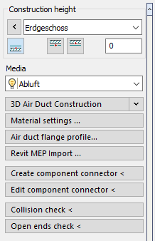
Construction height
In the Construction height section, you determine the height at which objects are drawn by setting the storey, reference edge and, if necessary, an offset.
Media
Use this drop-down list to select the medium for the drawing command.
3D Air Duct Construction
In the 3D Air Duct Construction section you will find the drawing and editing functions for air ducts.
Symbol functions
In this section you can make general settings to manage and edit symbols.
Symbols ...
Opens the Ventilation dialog, where all symbols and components of the trade can be found.
Air duct <
In the section Duct < you can define the settings for drawing 2D air ducts and execute the drawing commands.
Material settings ...
Opens the Material and Insulation dialog where you can specify default settings for the duct and insulation material to be used.
Air duct flange profile...
Opens the Flange profile dialog where you can select and assign manufacturer profiles or user-defined profiles.
Revit MEP Import...
With the command Revit MEP Import ... you can import pipe and duct networks that have been exported from Revit to Design 3D using the LINEAR command Handover to Design 3D, into the AutoCAD module Design 3D Pipe&Power. For the import, a d3d file is required in which the data on the MEP components and the pipe or duct topologies exported from Revit are stored.
After selecting the d3d file to be imported and specifying the pipe or duct sets to be used, the networks are imported automatically. Since not all situations or used components can be imported without errors, it is possible that gaps in the networks occur that require manual rework. Information about errors and deviations in the generation of the networks is listed in the Reports.
Create component connector <
With this command you can set a connection to a self-created component in order to connect a 3D pipe to it later, for example. After that, you can define the connection in more detail using the Edit component connector < command.
The button replaces the ANS command input in the command line.
Edit component connector
After you have set a connection to your component using the Create component connector < command, you can use Edit component connector < to define the connection in more detail, specifying the dimension and connector type, for example.
The button replaces the ANED command input in the command line.
Collision check <
Starts the collision check, which provides information on whether and where 3D components (independent of the trade) collide with each other. The basis for the collision check is the graphical representation of the pipes. The illustration with or without insulation affects the collision check. In case of errors, the Report dialog opens, where you can work through the detected collisions step by step.
The collision check also includes components from external references. If the check process takes too long, the collision check can be aborted by pressing the ESC key. Collisions found up to this point are then displayed in the Reports dialog.
Open ends check <
Starts the check for open ends. If open ends are found, the Reports dialog opens, where you can work through the open ends step by step. The basis for the Open ends check < is the graphical representation of the pipes.