Details on Render
Information about Render in 3D Pre-wall technology.
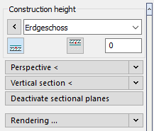
Construction height
In the Construction height section, you determine the height at which objects are drawn by setting the storey, reference edge and, if necessary, an offset.
Perspective <
The command Perspective allows you to set the perspective on your drawing, i.e. viewing direction, cropping, focal length, eye level and target level.
This allows you to set very effective and realistic perspectives on your plans in 3-dimensional planning, for example, to make them more vivid and transparent for the building owner. Detailed problems can thus very often be described with a few pictures instead of many words.
Click the Perspective < button on the left and determine the point and direction of view by specifying two points in the drawing.
Focal length
The focal length changes the horizontal angle of view from normal (50 mm) to an extreme wide angle (10 mm). Use the button to apply the changed setting to the drawing.
Eye level
The eye level is relative to the upper edge of the floor of the currently set storey. For for example, if you are on the 1st storey at 3 m, and you set the eye level to 1700 mm, the total eye level is 4700 mm.
Target height
The difference between eye level and target height defines the viewing direction in the vertical plane. The target height is also relative to the upper edge of the floor of the currently shown drawing.
A click on the button applies the set target height to the drawing.
Edit <
The button is used to apply the respective set value to the drawing.
Vertical section <
With this command you can place any section through your 3-dimensional planning and display it. This is how you can create wall views e.g. very easily. Click on the Vertical section < button on the left to specify the desired section.
Deactivate sectional planes
A simple click on this button disables the previously defined horizontal or vertical section planes and all objects in your drawing become visible again
Rendering ...
Once you have added materials to your drawing and set the display (for example, as a perspective), you can use the Rendering ... command to create a photorealistic image.
Using the drop-down list, you can select different presets for rendering and get a preview of them in the window above.
Rendering settings...
This button takes you to the CAD program's presets for rendering. For more details, please refer to the help of your CAD program.