Details on Display in 3D Construction
Information on parameterizing the display of ducts, pipes and electrical cable trays in 3D construction.
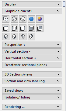
Display
Display symbols 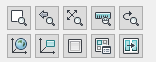
Use this command to control the display and define sections.
QuickLayer
With the QuickLayer you can comfortably switch on and off the layers of the individual components such as underlays or room contours. In the QuickLayer tool only the buttons of layers with objects are available.
Layer-Manager ...
Opens the dialog Layer-Manager.
ELayer <
This command (element-layer control) gives you the option of configuring a layer without knowing its name.
Presentation
In the Display area, you determine the quality in which your drawing is displayed and plotted on your screen.
Graphic elements
This command allows you to control the display of specific 3D objects, e.g. 3D air ducts, 3D pipes or panel heating elements.
Visual styles 
These are CAD commands that you can also select from the CAD menu View | Visual styles.
3D Views 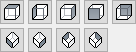
In this area, buttons are available for viewing your three-dimensional drawing.
Perspective <
The command Perspective < is allows you to set the perspective on your drawing, i.e. viewing direction, cropping, focal length, eye level and target level.
Vertical section <
With this command you can place any vertical section through your 3-dimensional planning and display it.
Horizontal section <
With this command you can place any horizontal section through your 3-dimensional planning and display it.
Deactivate sectional planes
A simple click on this button disables the previously defined horizontal or vertical section planes and all objects in your drawing become visible again
3D Sections/views
This command allows you to define, name and save multiple vertical sections in a 3D drawing. First, section lines are drawn at a certain height, which can then be used to create viewports with these section views at different scales in the layout.
Section and view labeling
The section and view label settings are also used in the 3D Sections/views command. You can also use the section and view labels to draw section lines in the model space. No 3D view is generated, only a section line is drawn.
Saved views
Enter a name for the currently set view in the input field and click the Save button to save the settings under this name. The view will then be added to the list. With Delete you can delete the view from the list again.
Isolating/Hiding
This command allows you to hide selected objects from your drawing in saved steps. The objects will not be deleted, they will only be hidden in all views until you undo the operation using the arrow keys.
Use the left arrow < to undo the individual fade operations. The right arrow > will take you back to the previous blanking.
The double arrow to the left << makes all objects visible again. The double arrow to the right >> hides all previously cropped objects.
If a drawing was saved with hidden elements, this will be reported the next time it is opened and you will be asked whether they should be shown again.
Rendering ...
Once you have added materials to your drawing and set the display (for example, as a perspective), you can use the Rendering ... command to create a photorealistic image.
Settings
You can use the Settings to make general presettings for editing and displaying drawings.
Inquire
You can use the inquire functions to access diverse information. Data about Distance , surface and ID point are displayed in the command line. Information such as List , Status and Time is shown in the CAD text window.
Drawing aids ...
Opens the CAD dialog Design settings where you can make global presettings. For more information, see the CAD Help.