Details about Constructing Pipes
Information about the command group Pipes in 3D Piping.
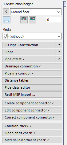
Construction height
In the Construction height section, you determine the height at which objects are drawn by setting the storey, reference edge and, if necessary, an offset.
(3D) Pipe construction
In this section you will find the commands for drawing 2D or 3D pipes.
Slope
In this section you define the slope for pipes to be constructed.
Pipe offset <
3D pipes crossing each other or colliding with other objects (like support columns) can be edited afterwards with a pipe offset to fix the collision.
Drainage connection <
This command allows you to connect consumers such as wash stands, showers or WCs to collector or down pipes. Make sure that all objects are located on their respective layers and that the layers are named according to the set layer key.
Pipeline corridor <
Use the command Pipeline corridor < to draw several parallel pipes according to the presettings at the same time.
Distance tables ...
You can store the distance values in a table so that you do not have to pay attention to maintaining distances to the walls when drawing pipes. If you have install the pipes with different distances depending on the type of building, room, etc., you can create a special distance table for each requirement.
Pipe class editor
Opens the Material editor, where you can compile the most frequently used materials into sets.
Revit MEP Import...
With the command Revit MEP Import ... you can import pipe and duct networks that have been exported from Revit to Design 3D using the LINEAR command Handover to Design 3D, into the AutoCAD module Design 3D Pipe&Power. For the import, a d3d file is required in which the data on the MEP components and the pipe or duct topologies exported from Revit are stored.
After selecting the d3d file to be imported and specifying the pipe or duct sets to be used, the networks are imported automatically. Since not all situations or used components can be imported without errors, it is possible that gaps in the networks occur that require manual rework. Information about errors and deviations in the generation of the networks is listed in the Reports.
Create component connector <
With this command you can set a connection to a self-created component in order to connect a 3D pipe to it later, for example. After that, you can define the connection in more detail using the Edit component connector < command.
The button replaces the ANS command input in the command line.
Edit component connector <
After you have set a connection to your component using the Create component connector < command, you can use Edit component connector < to define the connection in more detail, specifying the dimension and connector type, for example.
The button replaces the ANED command input in the command line.
Correct component connector <
The command Correct component connector < command allows you to correct the connection types, the nominal widths and, if necessary, the pressure stages of the component connections of individual components or all components of a type. You can use this command, for example, to correct the universal connections that were created during the Revit MEP import.
Collision check <
Starts the collision check, which provides information on whether and where 3D components (independent of the trade) collide with each other. The basis for the collision check is the graphical representation of the pipes. The illustration with or without insulation affects the collision check. In case of errors, the Report dialog opens, where you can work through the detected collisions step by step.
Open ends check <
The basis for the Open ends check < is the graphical representation of the pipes. A check for open ends is performed in the drawing.
Material assortment check <
If a material manufacturer changes its assortment and you reload an existing material table, individual fittings my no longer be available in the current data set. Clicking on this button will start a check, that will list all the components at the end that are no longer available in the current data set.
Built-in parts
In this section you will find the commands for placing built-in parts in a 2D drawing.
Manifold ...
Opens the Manifold dialog where you can construct the layout of a manifold in 2D or 3D to insert it in the drawing afterwards.