Details on 3D Air Duct
Information about the 3 D Air duct section in Air duct.
In this section you will find the drawing and editing functions for air ducts.
You are here:
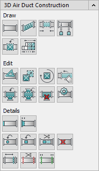
Draw
The commands of the Draw section are used to create ducts, flex pipes, built-in parts and devices.
| Button | Description |
|---|---|
| | Starts the drawing command for ducts. You can draw ducts from any starting points or from connection points of already drawn components. |
| | Starts the drawing command for flexible pipes. You can draw flexible pipes from any starting points or from connection points of already drawn components. |
| | Connects two open duct ends to each other. |
| | Connects existing ducts to drawn components such as outlets. |
| | Opens the last used component catalog where you can select component to draw. If the correct component catalog is not displayed, open the required component catalog (e.g. User components Ventilation) and Components. |
| | Opens the Device configuration dialog where you can configure and then draw in central air handling units. |


Edit
You can use the commands of the Edit section to make subsequent changes to drawn duct networks.
| Symbol | Description |
|---|---|
| | Allows you to set the angle of the component in various ways from the command line. The following setting options are available:
|
| | Allows you to move components in your drawing. You can move duct pieces, outlets and air grilles in ducts. Flex tube are automatically moved along during moving. |
| | Allows you to rotate components. The components are always rotated around the correct axis in 3D space. For example, if you choose an outlet, you have the option to adjust your outlet to a certain angle of the ceiling. To do this, enter an angle in the command line or point the angle with pointer. |
| | Allows you to align and connect duct sections together through a combination of rotating and moving. |
| | Allows you to insert branches into drawn ducts. |
| | Allows you to insert double branches into drawn ducts. |
| | Allows you to delete components that have already been installed. If you delete a branch, for example, the duct section will also be closed automatically. |
| | Allows you to edit components that have already been installed. |


Details
In this section you will find all commands that have to do with covers, cut-outs or duct section lengths, for example.
| Symbol | Description |
|---|---|
| | Allows you to attach and remove covers from connections. To remove covers, after activating the command, select the cover to be removed instead of a connection. |
| | Allows you to specify fitting lengths of connections and provide them with loose flanges. In the material list, additionally specified fitting lengths are shown and in the drawing the corresponding connections are provided with double white lines (loose flange). |
| | Allows you to provide ducts or pipes with rectangular, oval or round sockets. |
| | Allows you to provide ducts or pipes with rectangular, oval or round cutouts. Once you make a cutout in a duct, you can continue working on that cutout as you would on any other connection. In such cases, the program automatically suggests sockets or branch saddles when a duct is connected. |
| | Allows you to edit cutouts in ducts. For example, you can adjust dimensions of cutouts or change rectangular cutouts to round cutouts. |
| | Allows you to delete cutouts in ducts. |
| | Allows you to edit section lengths from ducts. |
| | Allows you to divide ducts into section lengths. Ducts are drawn as duct sections in your drawing. This has the advantage that you can process the sections more quickly and, for example, easily install and remove components such as silencers. The ducts you draw in one go are always created as a ducts section. For positioning and labeling, the section lengths must be divided. |
| | Allows you to join section lengths. |


