Details on Component (Device Configuration - Draw Central Device)
Information about the Component dialog in the Device configuration of the 3D Air duct construction.
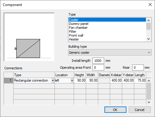
In this dialog you define a component type, the building type, installation length and connections of the component that you want to insert into the central device. You can also define interference spaces.
You are here:
Preview window
In the preview window you will see a schematic representation of the component with its connections. The view automatically adapts to the settings you make.
Type
From this list, select the component type that you want to insert into the central unit.
Building type
Drop-down list for specifying the design or version of the selected component type.
Install. length
Sets the installation length for the selected component.
Disturbance spaces
Here you can specify the dimensions for the interference spaces at the front/rear to access the device for operation and maintenance. The defined spaces are displayed as a cuboid on the Motion layer when drawing the device.
Connections
In the table you can add location, size and position of the connection ports for your component. Connector arrows are created at these connections, where you can continue drawing using the Draw duct command. You can attach several connections to one component.
| Column | Description |
|---|---|
| Type | Defines whether the connection port is rectangular, oval or round. |
| Position | Defines the position of the connection port. You can select left, right, front, back, above and below. |
| Height | Sets the height of the connection port for rectangular and oval connections. |
| Width | Sets the width of the connection port for rectangular and oval connections. |
| Diam. | Sets the connection diameter for round connections. |
| X-distance | Sets the distance of the connection to the outer edge of the component in the X direction. |
| Y-distance | Sets the distance of the connection to the outer edge of the component in the Y direction. A symmetric connection is suggested and the field Y‑distance will be completed accordingly. |
| Length | Determines how long the connection port on the component is. |