Verwarmingsplanning voor Revit
Met de oplossingen van LINEAR is een continue workflow in de verwarmingsplanning gegarandeerd. Van de conceptfase tot het maken van het TGA-model via de gebouwanalyse en de verwarmingslastberekening tot het productontwerp en de leidingnetberekening: maak uw planning snel en efficiënt met LINEAR op Revit.
The LINEAR workflow
Input:
Conceptstructuur van de architectuur met kamers, verdiepingen en functionele zones
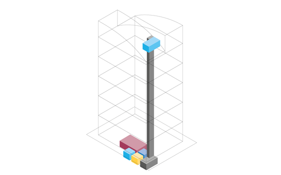
Output:
De ruimtebehoeften voor technische ruimten en pijpleidinggangen zijn vastgesteld
Work steps:
- Workflow voor een gezamenlijke planning in de vroege ontwerpfase
- Creëren van een conceptontwerp op basis van de eisenplanning
- Conceptueel ruimteontwerp (voorziening voor ruimtes)
- Lokaliseren en voordimensioneren van de ruimten voor technische uitrusting
- Lokaliseren en voordimensioneren van de leidinggangen
- Doorsnede-editor voor het concept van de leidinggangen
- Genereren van pijp- en kanaalelementen uit het corridorconcept
Input:
Architectuurmodel of -plan
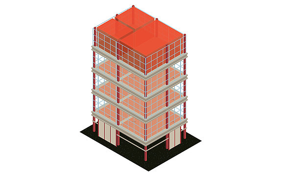
Output:
Model voor verder MEP ontwerp inclusief niveaus, zones & MEP kamers
Work steps:
- Overdracht van alle relevante vloerniveaus
- Automatisch aanmaken van aanzichten en plannen
- Zonering en creatie van MEP-ruimten
- Verrijking van het model met relevante informatie
- Parameterbeheer voor de toewijzing van in het project gebruikte parameters
- Optioneel voor 2D-sjablonen: Eenvoudige heropbouw van het gebouw in 3D
Input:
Model voor het MEP ontwerp inclusief niveaus, zones & MEP kamers
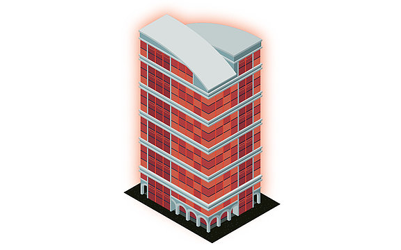
Output:
Berekende warmtebelasting
Work steps:
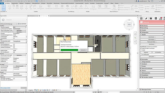
- Krachtige gebouwanalyse als basis voor de berekening van de verwarmingsbelasting
- Optionele analyse van de topografie van het terrein
- Automatische kartering van de gebouwstructuur (gebouwdelen, verdiepingen en kamers)
- Identificatie en gezamenlijke correctie van modelleringsfouten in overleg met de architect
- U-waarde berekening en toevoeging van ontbrekende berekeningsparameters
- Automatische warmtelastberekening voor het project, de verdiepingen en alle kamers
- Overname van alle relevante waarden in het model
Input:
Berekende warmtebelasting
Output:
MEP-model met gedimensioneerde verwarmingscomponenten
Work steps:
- Dimensionering van radiatoren, convectoren of paneelverwarmingssystemen op basis van de warmtebelastingberekening
- Vergelijking van varianten aan de hand van gecontroleerde datasets van fabrikanten
- Overname van de gedimensioneerde componenten in het model
- Naar keuze automatische of handmatige plaatsing van componenten
- Bidirectionele aanpassingen in het model of in de dimensionering
- Overname van alle relevante waarden in het model
Input:
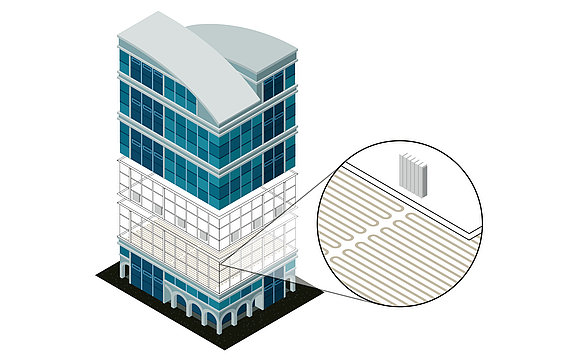
MEP-model met gedimensioneerde verwarmingscomponenten
Output:
MEP-model met geoptimaliseerde systemen en de voltooide leegteplanning
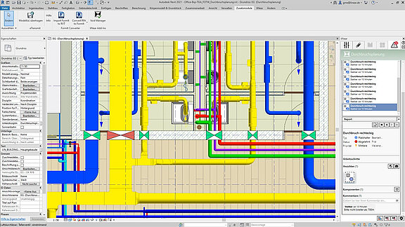
Work steps:
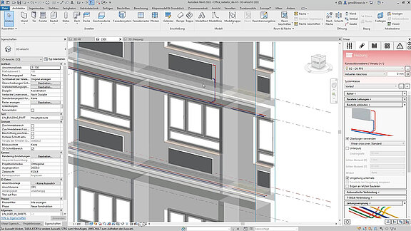
- Snelle opbouw van het leidingnet als enkele leiding of als parallelle leidingen
- Automatische aansluiting van alle verbruikers
- Installatieontwerp neutraal of met behulp van uitgebreide CAD-bibliotheken van fabrikanten
- Specificatie van berekeningsrelevante specificaties (bijv. toewijzing van leidingmaterialen, instellingen van kleppen, specificatie van isolatie en omgevingstemperaturen)
- Vergelijking van varianten aan de hand van gecontroleerde datasets van fabrikanten (bijv. leidingsystemen)
- Berekening van bestaande netwerken door vaststelling van afzonderlijke of alle afmetingen
- Herdimensionering van het verwarmingsleidingnet op basis van de berekening
- Gekleurde weergave van alle resultaten direct in het model (LINEAR datakleuring)
- Leegstandsplanning inclusief coördinatie via BCF en IFC
Input:
Berekend en geoptimaliseerd netwerk van verwarmingsbuizen
Output:
Definitief verwarmingsontwerp inclusief model voor overdracht naar het coördinatiemodel en berekende resultaten inclusief materiaallijsten
Work steps:
- Opslag van alle inputs en berekeningsresultaten in het model
- Publicatie van selecteerbare waarden als gedeelde parameters
- Automatische labeling van het model
- Toevoeging van eigen parameters en meta-informatie
- Afdrukken van de resultaten in gestandaardiseerde vormen
- Overdracht van de resultaten en het model in alle relevante formaten
Input:
Conceptstructuur van de architectuur met kamers, verdiepingen en functionele zones
Output:
De ruimtebehoeften voor technische ruimten en pijpleidinggangen zijn vastgesteld
Arbeitsschritte:
- Workflow voor een gezamenlijke planning in de vroege ontwerpfase
- Creëren van een conceptontwerp op basis van de eisenplanning
- Conceptueel ruimteontwerp (voorziening voor ruimtes)
- Lokaliseren en voordimensioneren van de ruimten voor technische uitrusting
- Lokaliseren en voordimensioneren van de leidinggangen
- Doorsnede-editor voor het concept van de leidinggangen
- Genereren van pijp- en kanaalelementen uit het corridorconcept
Input:
Architectuurmodel of -plan
Output:
Model voor verder MEP ontwerp inclusief niveaus, zones & MEP kamers
Arbeitsschritte:
- Overdracht van alle relevante vloerniveaus
- Automatisch aanmaken van aanzichten en plannen
- Zonering en creatie van MEP-ruimten
- Verrijking van het model met relevante informatie
- Parameterbeheer voor de toewijzing van in het project gebruikte parameters
- Optioneel voor 2D-sjablonen: Eenvoudige heropbouw van het gebouw in 3D
Input:
Model voor het MEP ontwerp inclusief niveaus, zones & MEP kamers
Output:
Berekende warmtebelasting
Arbeitsschritte:
- Krachtige gebouwanalyse als basis voor de berekening van de verwarmingsbelasting
- Optionele analyse van de topografie van het terrein
- Automatische kartering van de gebouwstructuur (gebouwdelen, verdiepingen en kamers)
- Identificatie en gezamenlijke correctie van modelleringsfouten in overleg met de architect
- U-waarde berekening en toevoeging van ontbrekende berekeningsparameters
- Automatische warmtelastberekening voor het project, de verdiepingen en alle kamers
- Overname van alle relevante waarden in het model
Input:
Berekende warmtebelasting
Output:
MEP-model met gedimensioneerde verwarmingscomponenten
Arbeitsschritte:
- Dimensionering van radiatoren, convectoren of paneelverwarmingssystemen op basis van de warmtebelastingberekening
- Vergelijking van varianten aan de hand van gecontroleerde datasets van fabrikanten
- Overname van de gedimensioneerde componenten in het model
- Naar keuze automatische of handmatige plaatsing van componenten
- Bidirectionele aanpassingen in het model of in de dimensionering
- Overname van alle relevante waarden in het model
Input:
MEP-model met gedimensioneerde verwarmingscomponenten
Output:
MEP-model met geoptimaliseerde systemen en de voltooide leegteplanning
Arbeitsschritte:
- Snelle opbouw van het leidingnet als enkele leiding of als parallelle leidingen
- Automatische aansluiting van alle verbruikers
- Installatieontwerp neutraal of met behulp van uitgebreide CAD-bibliotheken van fabrikanten
- Specificatie van berekeningsrelevante specificaties (bijv. toewijzing van leidingmaterialen, instellingen van kleppen, specificatie van isolatie en omgevingstemperaturen)
- Vergelijking van varianten aan de hand van gecontroleerde datasets van fabrikanten (bijv. leidingsystemen)
- Berekening van bestaande netwerken door vaststelling van afzonderlijke of alle afmetingen
- Herdimensionering van het verwarmingsleidingnet op basis van de berekening
- Gekleurde weergave van alle resultaten direct in het model (LINEAR datakleuring)
- Leegstandsplanning inclusief coördinatie via BCF en IFC
Input:
Berekend en geoptimaliseerd netwerk van verwarmingsbuizen
Output:
Definitief verwarmingsontwerp inclusief model voor overdracht naar het coördinatiemodel en berekende resultaten inclusief materiaallijsten
Arbeitsschritte:
- Opslag van alle inputs en berekeningsresultaten in het model
- Publicatie van selecteerbare waarden als gedeelde parameters
- Automatische labeling van het model
- Toevoeging van eigen parameters en meta-informatie
- Afdrukken van de resultaten in gestandaardiseerde vormen
- Overdracht van de resultaten en het model in alle relevante formaten
Features
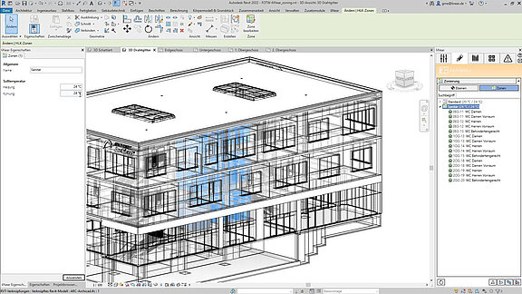
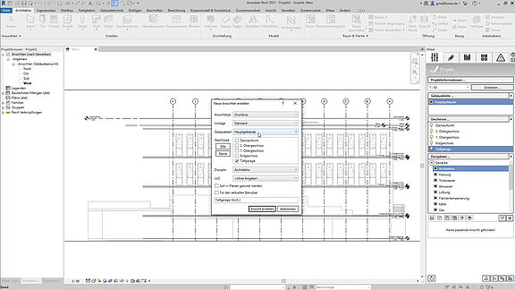
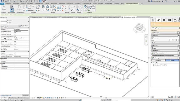
Maken en controleren van weergaven
- Wizard voor het maken van weergaven voor 3D-aanzichten, plattegronden, plafondplannen en gebiedsplannen
- Snelle commando's voor 3D-selectieboxen
- Snelle commando's voor werksecties
- Automatisch sorteren en toewijzen van aanzichten
- Suggesties voor de meest geschikte aanzichten
- Automatische LOG-toewijzing aan aanzichten
- Beeldfilters
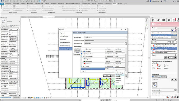
Taakbeheer
- Toewijzen van verantwoordelijkheden voor taken die automatisch (bijv. uit de berekeningen) of handmatig worden aangemaakt.
- Instellen van deadlines en prioriteiten voor taken
- Bijhouden van de status van taken
- Definitie van vooraf gedefinieerde workflows voor de voltooiing van taken
- Screenshots, opmerkingen, posities toevoegen aan taken
- Delen en toewijzen van taken aan deelnemers via BCF
Etikettering en dimensionering
- Automatische etikettering
- Toevoeging van eigen parameters en meta-informatie
- Automatische dimensionering
Familie en bibliotheekbeheer
- Centrale levering van alle noodzakelijke componenten voor uw project
- Componenten of configuratoren geschikt voor de actieve discipline
- Gefilterd op actieve discipline, gebruik in het project en opslaglocatie (lokaal of map in het netwerk)
- Gesorteerd in componentgroepen voor snelle oriëntatie
- Meerdere plaatsingscommando's voor families (plaatsen, vervangen, alles vervangen, op raster plaatsen)
- Integratie van eigen familiebibliotheken
- Intelligente zoekfunctie
- Opnieuw selecteren en plaatsen van een component in het model
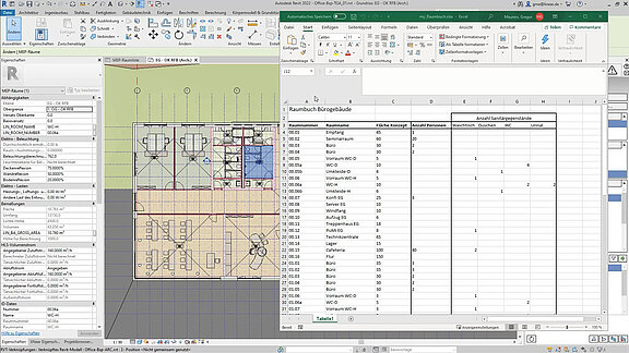
Tabel van de verdiepingen
- Automatische import van verdiepingen uit het architectuurmodel
- Controle van de verdieping in het constructievlak / offset gebied (+/-)
- Eenvoudig creëren van verdiepingen en werkniveaus
- Aparte vloertabel voor meerdere gebouwdelen (bijv. voor split levels)
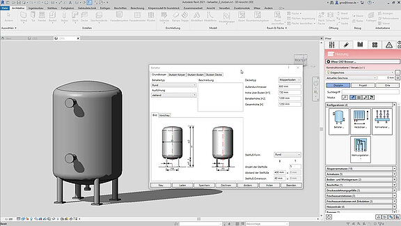
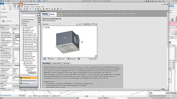
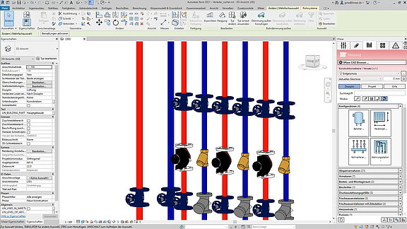
Fabrikantenfamilies (CAD-browser)
- Uitgebreide CAD-bibliotheken met beproefde onderdelen van onze talrijke industriële partners.
- Meer dan 6 miljard mogelijke componenten en componentencombinaties
- Directe plaatsing van componenten van de originele fabrikant in uw model
- Meerdere plaatsingsmodi (plaatsen, vervangen, alles vervangen)
- Configurators voor complexe componentencombinaties (bv. cascadesystemen)
- Integratie van technische en commerciële gegevens (bv. artikelnummers en verpakkingseenheden)
- Herkenning van en rekening houden met netwerkberekeningen
Interoperabiliteit en samenwerking
- IFC importconfiguratie
- Classificatie van IFC of andere structuren
- Excel import en export
- Rapporten en takenbeheer voor BCF-uitwisseling (incl. chatfunctie)
- Gemeenschappelijke thema's en statustracking voor BCF-uitwisseling
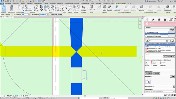
Botsingscontrole
- Detectie en weergave van alle soorten botsingen binnen een project of tussen verschillende projecten
- Controle op botsingen tussen architectuur en alle disciplines
- Collision check tussen twee disciplines of een discipline met architectuur
- Collision check tussen enkele of meerdere categorieën (bijv. muren en leidingen)
- Collision check tussen enkele of meerdere systemen (bijv. gas en uitlaat)
- Automatisch aanmaken van taken voor elke botsing in het tabblad Rapport en Taak
- Opslaan en laden van voorgedefinieerde configuraties
Conceptuele hulpmiddelen
- Workflow voor collaboratieve planning in de vroege ontwerpfase
- Dimensionering van technische ruimtes
- Conceptuele ruimtebehoefteplanning (voorziening voor ruimtes)
- Doorsnede-editor voor het lijngangconcept
- Herdimensionering van "voorzieningen voor ruimten
- Genereren van buis- en kanaalelementen uit het corridorconcept
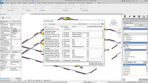
Parameterbeheerder en classificatie-instrument
- Toewijzing van liNear parameters aan eigen gedeelde parameters in een projectafhankelijke mapping tabel.
- Zoek- en filterfuncties voor het mappen of overschrijven van parameters
- IFC-classificatie (om de IFC-uitvoer te verbeteren)
- Laden en opslaan van voorgedefinieerde projectstandaarden
- Toewijzing van classificatieparameters aan componenten en modelelementen om deze te vullen met waarden
- Structureren van de classificatie van componentgroepen in de IFC-export
- Classificatie van componenten gerelateerd aan kostengroepen voor nauwkeurige kostenramingen
- Definitie van de informatie die aan het model wordt verstrekt (informatieniveau)
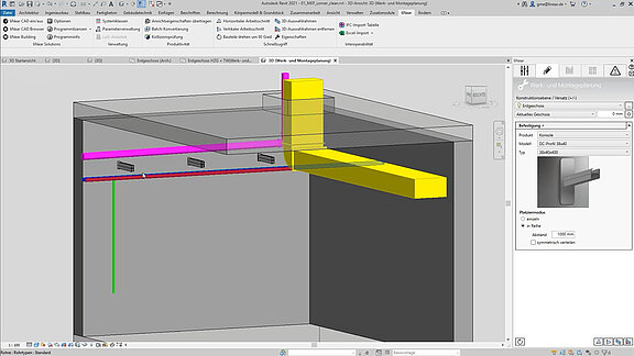
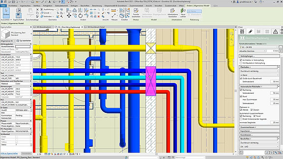
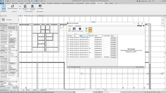
Planning van sleuven en doorbraken
- Handmatige plaatsing
- Automatische plaatsing
- Plaatsing op basis van gerefereerde modellen
- BCF-export (optioneel incl. IFC) voor samenwerkingsdoeleinden
- BCF import voor statusafstemming
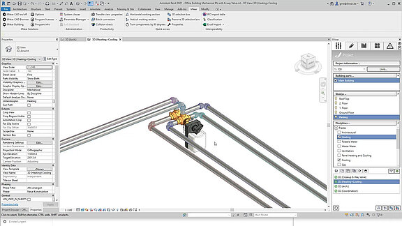
Controle van de zichtbaarheid
- Met één klik zichtbaarheid regelen voor projectielen
- Zichtbaarheidscontrole met één klik voor disciplines
- Zichtbaarheidscontrole met één klik voor onderdelengroepen (bijv. systemen, isolatie, enz.)
- Zichtbaarheidscontrole met één klik voor bouwonderdelen
Taalkeuze voor interface en afdrukken
Wij stellen u niet minder dan zeven talen ter beschikking, die u naar believen kunt gebruiken en combineren, hetzij als interfacetaal, hetzij als printtaal. Op die manier is het mogelijk om in de ene taal te plannen en in een andere taal te drukken. Dit is een groot voordeel, vooral voor internationale projecten, omdat tijdrovende vertalingen niet meer nodig zijn. Er zijn geen extra kosten voor de taalpakketten.
De volgende talen worden momenteel ondersteund:
- Duits
- Engels
- Frans
- Nederlands
- Russisch
- Turks
- Italiaans
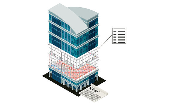
Onderdelenlijst met artikelnummers
- Duidelijke en begrijpelijke berekeningsresultaten en volledige servicespecificaties
- Gedetailleerde stuklijsten met artikelnummers en materiaaltests
- Servicespecificaties en stuklijsten in verschillende uitvoerformaten (Windows afdruk, Excel, tekst, UGS, GAEB, ASD)
Systeemtabel en snelle selectie
- Centraal beheer van systeemklasse-eigenschappen
- Intuïtieve systeemtabel
- Snelle selectie van het systeem
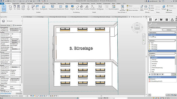
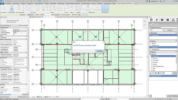
MEP model creatie (architectuur)
- Automatisch of handmatig aanmaken van MEP-ruimtes
- Tool voor zonering
- Architecturale functies voor eenvoudige hermodellering van 2D-architectuurplannen
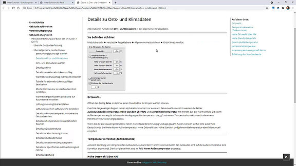
Ondersteunde normen
LINEAR heeft altijd gestaan voor normconforme berekening en ontwerp. Het is onze zorg om altijd de nieuwste normen aan te bieden en het aanbod van nationale en internationale normen voortdurend uit te breiden. Een actueel overzicht van alle ondersteunde normen vindt u in onze LINEAR Knowledge Base.
Automatisch intekenen van gedimensioneerde onderdelen
- Automatische plaatsing van radiatoren, convectoren en paneelverwarmers in uw CAD-model
- Automatische etikettering van overgedragen componenten
- Overbrengen en bijwerken van gedimensioneerde componenten in uw model en van uw model in de dimensionering
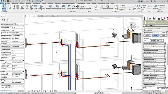
Automatische detectie van het leidingnet
- Detectie van getrokken leidingen direct in het model en analyse van het systeem
- Herkenning van alle geïntegreerde componenten
- In aanmerking nemen van in het model geïntegreerde technische gegevens
- Herkenning van geconstrueerde afmetingen voor optionele beschouwing in de netwerkberekening
- Eenvoudige toewijzing van externe componenten om in de netwerkberekening in aanmerking te nemen
Berekening van het leidingnet met herdimensionering
- Automatische berekening en dimensionering van alle componenten van het netwerk van verwarmingsbuizen
- Inachtneming van bepaalde randvoorwaarden zoals grenswaarden voor snelheden en wrijvingsweerstand van de buis (R-waarde)
- Bepaling en vergelijking van varianten van buismaterialen en componenten incl. datasets van originele fabrikanten met werkelijke producteigenschappen
- Berekening direct in het model incl. herdimensionering
- Hydraulische berekeningen met overdracht van prestatiegegevens van familiekarakteristieke waarden
- Berekening van meerdere systemen in één model
- Selectie van geschikte (fabrikant) componenten op basis van de berekeningsresultaten
- Opslaan van parameters direct in het model met optionele overweging in de IFC-export
- Interface voor ventieldatasets, afsluiters, drukverschilregelaars, volumestroomregelaars, regelventielen, regelkleppen en vaste weerstanden
- Visualisatie van de resultaten met behulp van liNear Data Coloring (afmetingen, materialen, snelheden, ongunstige stromingspatronen en nog veel meer)
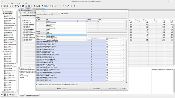
Analyse van het gebouw
- Registratie en analyse van het gebouw, met inbegrip van de informatie die nodig is voor de berekening van de belasting (bv. gewenste temperaturen voor verwarming en koeling).
- Definitie en overdracht van verdere gebouwparameters (bv. namen van appartementen).
- Herkenning van gebouwdelen, verdiepingen, zones en kamers
- Automatische overdracht van alle gebouwdelen, verdiepingen, kamers en ruimtecomponenten inclusief kamer- en aangrenzende temperaturen rechtstreeks uit het Revit-model
- Herkenning en inachtneming van terreinbenadering
- Automatische controle van modelleringsfouten in het architectuurmodel voor kennisgeving aan de architect
Hydraulisch balanceren van complexe systemen
- Hydraulische berekeningen met overdracht van prestatiegegevens van familieparameters
- Berekening van meerdere systemen in één model
- Berekening ook van netwerken met verschillende regelniveaus
- Niet alleen rekening houden met de distributienetten, maar ook met de generator
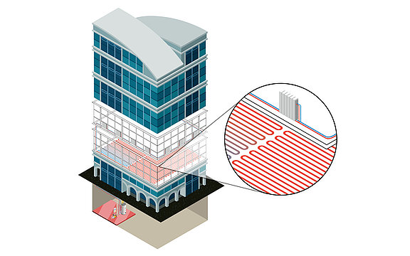
Dimensionering van de paneelverwarming
- Dimensionering en ontwerp van paneelverwarmingssystemen (vloer, wand en plafond) op basis van de berekening van de verwarmingsbelasting
- Eenvoudige vergelijking van varianten
- Bepaling en toewijzing van leidingen, verdeelstukken, verdeelaansluitingen en regelcomponenten (bijv. kleppen)
- Automatisch maken van leidingschema's
- Uitgebreide gegevenssets van fabrikantproducten voor radiatoren, convectoren en paneelverwarmingssystemen
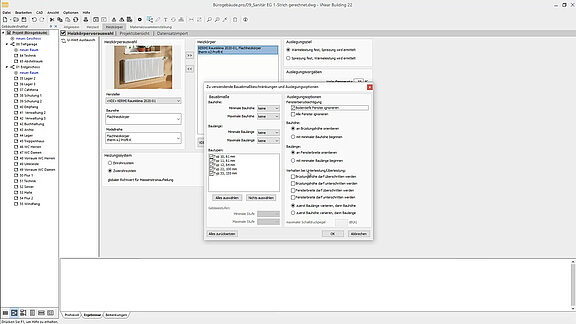
Dimensionering van radiatoren en convectoren
- Dimensionering van radiatoren en/of convectoren voor elk vertrek op basis van de berekening van de verwarmingsbelasting.
- In aanmerking nemen van reeds in het model geïntegreerde radiatoren en nieuwe dimensionering, ontwerp en actualisering van het model
- Eenvoudige vergelijking van varianten
- Dimensionering voor tweepijps- en éénpijpssystemen
- Bepaling en toewijzing van leidingen, verdelers, verdeleraansluitingen en regelcomponenten (bijv. kleppen)
- Uitgebreide gegevenssets van fabrikantproducten voor radiatoren, convectoren en paneelverwarmingen
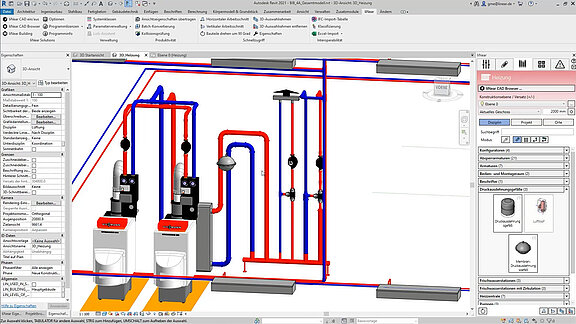
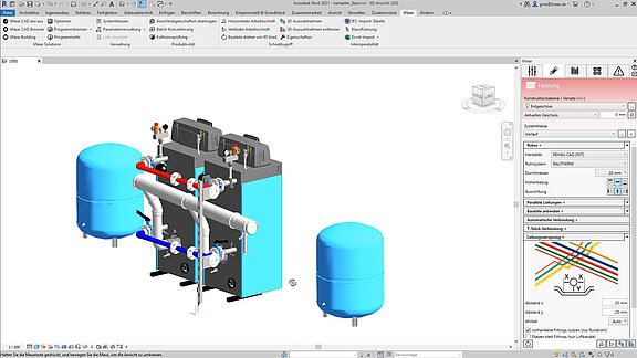
Bouwgereedschap
- Opdracht voor pijpleidingen, inclusief bepaling van de systeemklasse
- Automatisch verbinden van leidingen, inclusief noodzakelijke overgangen (autorouting)
- Automatische T-stuk verbinding
- Opdracht voor het springen van leidingen om botsingen op te lossen
- Configuratoren voor radiatoren, convectoren, verdelers, tanks
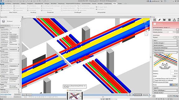
- Ontwerp van parallelle leidingen
- Ontwerp van paneelverwarming ook met ronde objecten
- Ontwerptools voor bevestigingen, flenzen, leveringslengtes, enz.
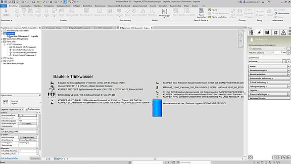
- Legende functie
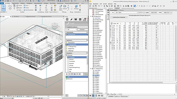
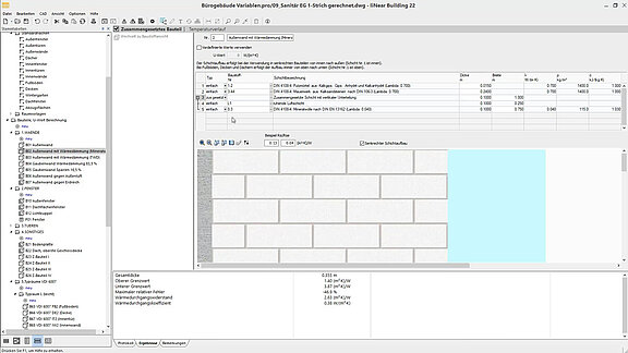
Berekening van de verwarmingsbelasting
- Automatische overdracht van alle gebouwdelen, vloeren, kamers en ruimtecomponenten rechtstreeks vanuit het CAD-model
- Berekeningen van de verwarmingsbelasting op basis van talrijke nationale en internationale normen
- Snelle en eenvoudige berekening van U-waarden
- Parametrisch datamodel voor eenvoudige wijzigingen
- Automatische update na wijzigingen in het architectuurmodel
- Uitgebreide materiaalbibliotheek voor het definiëren van bouwcomponenten
- Snellere invoer door creatie van standaardcomponenten
Feature videos

Feature videos