Details on the Additional Commands of the Assistants
Information about additional commands of the assistants.
In the lower section of the assistants there are a number of buttons with additional commands, which are explained in detail below.
You are here:
Set construction layer
 : Use this command to draw auxiliary lines on a separate, magenta-colored layer named Construction. By clicking the button, the Construction layer will be created and activated as the current layer automatically. You may then draw your auxiliary construction. Clicking the button again will reactivate the layer you have used before.
Delete construction layer
 : Click this button to delete the entire contents of the construction layer.
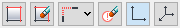
Switch button
The third button from the left can be assigned with five different commands, which are each explained in more detail below Click the triangle of the Switch button to open the fly out menu and to set the desired command.
 L-connecting: This command allows you to extend or trim two lines to the common intersection point. When trimming, select the parts of the line that should be preserved. For waste water pipes and other media with chamfer it will automatically be made use of a connection of less than 45°.
Any existing settings for a pipe that originate from the LINEAR Analyse Programs - e.g. material, length, labeling - are lost when the pipes are connected, as new objects are created in the process.
 T-connecting: With this function a line is being extended or being shortened to a limit edge. For waste water pipes and other media with chamfer it will automatically be made use of a connection of less than 45°. The position of the first mouse click determines the direction of the chamfer. After selecting the two pipes to be connected or shortened, the connected pipe with chamfer is displayed and you have the option to increase or decrease the chamfer or to have the connection drawn without chamfer. Use the right mouse button to open the context menu and select the corresponding entry or enter g for a larger chamfer, k for a smaller chamfer or o for no chamfer in the command line and confirm with Enter.
Any existing settings for a pipe that originate from the LINEAR Analyse Programs - e.g. material, length, labeling - are lost when the pipes are connected, as new objects are created in the process.
 Get properties: This command determines the medium of the selected drawing element. If you have chosen the Scheme planning Heating assistant and select a sewage water pipe using the command Get properties the current medium will be set on Sewage water an all media of the Sanitary trade will be provided.
 Adjust crosshair angle: This command allows the crosshair to be set in adjustable angular degrees, similarly to setting the title block on a conventional drafting machine. The UCS will not be changed in the process. You can specify the angle in numerical terms in degrees or percent, show the zero line through two points or orient the crosshair to an object in the drawing. In order to turn the crosshair back to its standard setting, restart the command and enter angle 0.
After you have clicked , you can enter more options in the command line.
-
Show When you type z and Enter in the command line, you can determine the rotation of the crosshair by means of two points.
-
Percent: When you type % and Enter in the command line, you can determine the rotation of the crosshair by means of an ascending or negative slope in percent.
-
Object: When you type o and Enter in the command line, you can determine the rotation of the crosshair by means of the selection of an object. Click an object (e.g. a pipe) where the crosshair shall be oriented.
 Zoom to scale: This button is used to set the scale of a drawing in a viewport so you can plot the drawing in the correct scale.
Delete report layer
 : If errors occur during the calculation using the LINEAR Analyse programs, the affected positions are assigned a report marker
 ![]() during the calculation step. Under certain conditions these markers can disturb the error correction. By clicking the button, all report markers in the drawing are deleted.
during the calculation step. Under certain conditions these markers can disturb the error correction. By clicking the button, all report markers in the drawing are deleted.
90°-/45° Drawing mode
The following two commands are available only if Russia is selected as the region in the Configuration.
 0° degree: This is the standard setting for the drawing mode. The crosshair is rectangularly positioned to the drawing surface. Click the button to turn back to the conventional position in case the crosshair has been rotated before. You can rotate the crosshair during the drawing process without stopping the multi-pipe route or pipe command.
 45° degree: Use the 45° drawing mode to create isometric and axonometric drawings. Click to rotate the crosshair 45°. You can rotate the crosshair during the drawing process without stopping the multi-pipe route or pipe command. To turn the crosshair back to the conventional position, click the 0° button .
Axonometry
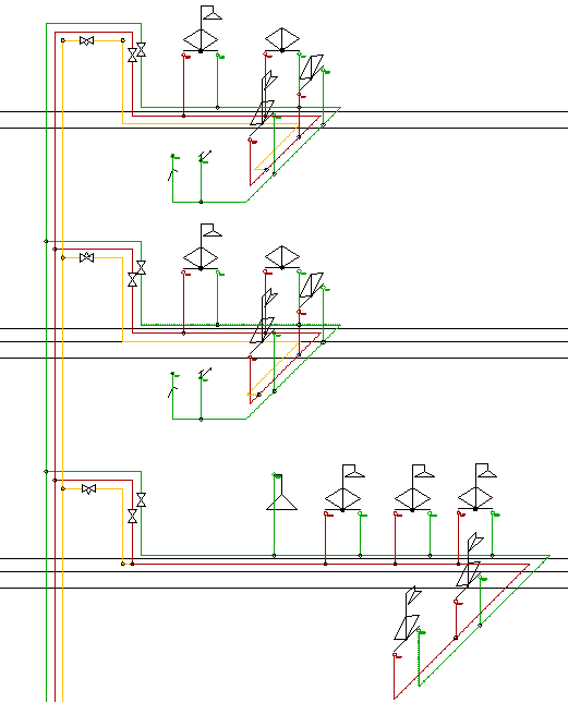
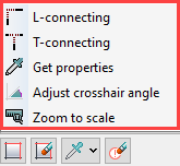
In order to create axonometric drawings according to SNiP standard, you can rotate the crosshair during the running multi-pipe route or pipe command. Draw symbols afterwards, the angle of the pipe run will be automatically detected and the symbol will be rotated accordingly after it has been placed in the drawing.
| Before placing the symbol | After placing the symbol |
|---|---|
 | 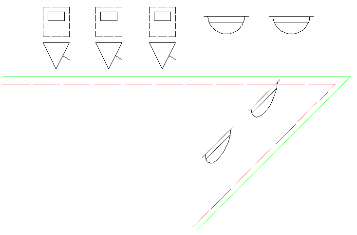 |
If you create your own scheme symbols, they only need to be prepared for the front view.
Use the Axonometry assistants to create computable axonometries.
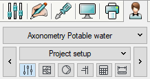
Axonometry assistants are available only if Russia is selected as the region in the Configuration.