Details on Component dialogs
Information about the component dialogs when drawing ducts in 3D Air Duct Construction.
In the properties dialogs of the components for 3D air ducts, you define the dimensions of the respective component, the reference edge for drawing in, the material and, if necessary, the insulation and flange profile.
You are here:
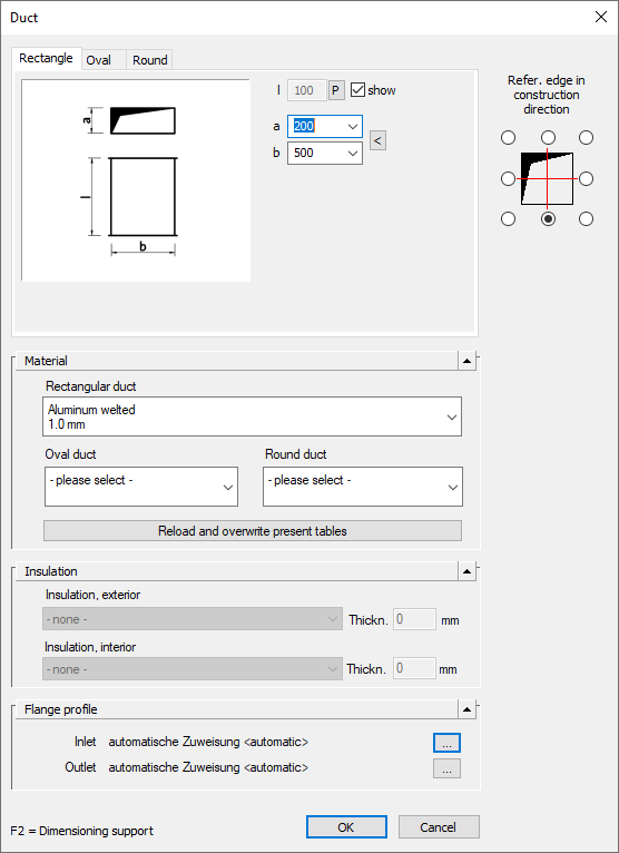
Rectangle, Oval, Round
Depending on what settings you have already made and depending on the component, you will be offered different variants of the component for use in rectangular, oval and round air ducts on different tabs of the dialog.
Using the fields and options to the right of the part preview, you can specify the dimensions of the part to be drawn in and define part-dependent settings for drawing. When you change the dimensions, the preview automatically updates. The fields with the component dimensions are marked with variables. The assignment of the variables to the corresponding dimensions of the component is also displayed in the preview. For variables with the show checkbox, you have the option to pick the dimension from the drawing. To do this, activate the checkbox and you will be prompted to pick the dimension in the drawing after confirming your entries (OK).
Reference edge in construction direction
Use the radio buttons to determine the reference edge for drawing in the component.
Material
In the Material section, you specify whether a rectangular duct, oval duct or round duct is used by selecting the corresponding checkbox. Using the drop-down lists, you can determine the material to be used.
Reload and overwrite existing tables
Allows you to reload the material table saved in the drawing. This allows any materials that may have been lost to be recovered. If reloading the table is not sufficient, the materials must be reassigned to the components.
Insulation
In the Insulation section, you can specify where the insulation is to be placed by selecting the appropriate checkbox. Using the drop-down lists, you can determine the insulation material to be used and specify the measurements of the insulation in the Thickn. input field.
Flange profile
The button  opens the Flange profile dialog where you can define the flange profile elements for the Inlet and the Outlet of the duct.