Details on Configuration – Radiators in CAD
Information about Radiators in CAD section in the configuration of Building.
Specifies the display of radiators or cooling convectors and their labels.
There are program versions with different scope of services. This tab is not available in all versions.
You are here:
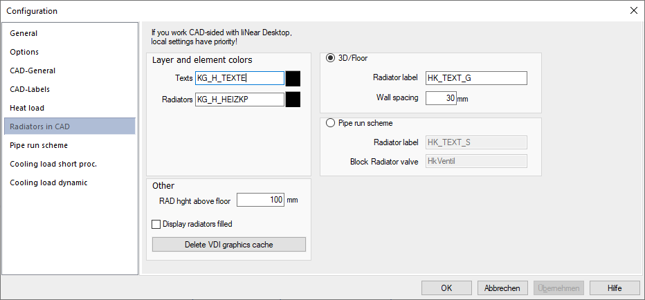
Defines whether a single radiator or cooling convector is to be inserted into the drawing as a three-dimensional or two-dimensional element when drawing. Moreover, you can determine the names and colors of the label layers.
Layer and element colors
Defines the names of the layers, on which the label texts and their frames and the radiator or cooling convector blocks and their supply and return water pipes are drawn. Clicking the color fields opens the Choose Color dialog, where you can specify the element colors used.
These functions are only available in conjunction with AutoCAD and only come into effect if you draw or label radiators or cooling convectors using an AutoCAD version without LINEAR CAD. If you are working with CAD, the settings there have priority in the Configuration on the Planning tab.
3D/Floor plan and Pipe run scheme
3D/Floor plan
Radiators and cooling convectors are drawn as three-dimensional blocks in the floor plan (3D display). You can specify the blocks for radiator or cooling convector display and labeling as well as the wall distance in mm for this purpose. The height above floor (RAD hght above floor) is specified in the Other section.
Pipe run scheme
Radiators and cooling convectors are drawn as three-dimensional blocks in the floor Pipe run scheme. For this purpose, you can specify the blocks for the radiator or cooling convector display, for the labeling and the thermostatic valve. The height above floor (RAD hght above floor) is specified in the Other section.
These functions are only available in conjunction with AutoCAD and only come into effect if you draw or label radiators or cooling convectors using an AutoCAD version without LINEAR CAD. If you are working with CAD, the settings there have priority in the Configuration on the Planning tab.
Other
RAD hght above floor
Radiators and cooling convectors are drawn in 3D displays or pipe run schemes with the specified height above the insertion point (floor). The height is to be specified in millimeters.
Display radiators filled
Activated: Radiators and cooling convectors are inserted into the CAD drawing fully filled.
Deactivated: Radiators and cooling convectors are inserted into the CAD drawing by default.
If you work with LINEAR CAD and would like to subsequently display already drawn radiators or cooling convectors filled, you can set this in the Configuration of CAD LINEAR and have the radiators or cooling convectors updated in Building LINEAR.
If you have not drawn in the radiators with LINEAR CAD, but are working with a pure CAD version, the setting has to be made before drawing in. If you would like to change the display afterwards, you first have to delete the radiators or cooling convectors, clean up the drawing (i.e. delete the block definition that is now no longer used) and then redraw the radiators or cooling convectors.
These functions are only available in conjunction with AutoCAD and only come into effect if you draw or label radiators or cooling convectors using an AutoCAD version without LINEAR CAD. If you are working with CAD, the settings there have priority in the Configuration on the Planning tab.
Delete VDI graphics cache: Empties the buffer in which the VDI geometries for the display of radiators and cooling convectors in the CAD program are temporarily stored.