Details on How to Set Up a Project
Information about how to set up a project.
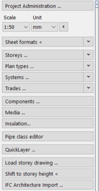
Project administration...
Opens the Project administration dialog where you can edit all project data and manage project files.
Scale/Unit
Sets the scale and unit used in the project. Scale and units influence the display of labels and dimensions and the output of data.
Memo
Opens the Memo dialog where you can save notes about your drawing, e.g. editing notes. The memo is saved with the current drawing and can be set to pop-up automatically when the drawing file is opened.
Sheet formats <
In the Sheet formats section you can set DIN formats and free formats and insert them into your drawing. The colors for the drawing frame and other lines such as trimming margin and fold marks can be freely selected.
Storeys ...
The section displays existing Storeys. Clicking the Storeys ... button opens the Storey Table dialog, where you can manage your storeys.
Plan types ...
The Plan types ... section shows information about scale, line styles for axes, hidden lines, dimensions and layer codes for the plan type name. Have existing plan types displayed, control layers with the contained layer codes if necessary or open the Plan type table via the Plan types ... button, in which you can enter, edit and delete plan types.
Systems ...
The Systems section shows an overview of the systems that have been created. Systems can be used to further subdivide complex drawings. Clicking the Storeys ... button opens the Systems dialog, where you can enter, edit and delete storeys.
Trades ...
The Trades ... section displays the available trades and allows you to activate a trade. Clicking the Trades ... button opens the Trades dialog, where you can create your own trades and assign the layer codes, the compilation of the command groups, the associated media, the licensed manufacturer catalogs and the toolbars.
Components ...
Opens the Components ... dialog where you can change the predefined attributes for the available components (e.g. the colors and line widths used for the layers).
Media ...
Opens the dialog Media table, where you manage and parameterize all available media, for example gas, potable water, waste water, supply air or extract air. The properties of the media layers, such as layer code, color, line type and line thickness and, if necessary, a chamfer value, are already predefined. All settings you make here are saved in the current drawing. If you would like to change certain settings permanently, create a corresponding template file.
Insulation ...
Opens the Insulation materials dialog where you can parameterize insulation materials and define and create your own insulation materials for interior and exterior insulation. All settings you make here are saved in the current drawing. If you would like to change certain settings permanently, create a corresponding template file.
Pipe class editor
Opens the Material editor, where you can compile the most frequently used materials into sets.
External references
Opens the External references window. External references are drawings or image files that you just load in order to display in your drawing. They can be used sensibly when, for example, you are working on architectural plans that change frequently during the course of the project.
Reference point
In order to be able to position external references or several storey drawings precisely one on top of another, there must be a sensible common reference point set in the drawings. Ideal is a point that is easy to find and lies in the same place in all of the drawings. For example, the corner of a stair well or elevator shaft. Set this position as the reference point for all drawings. This will be used as the insertion point when inserting external references.
Load storey drawing ...
Opens a dialog where you can load a dwg file (floor drawing) as an external reference in the current drawing. The title line of the dialog that indicates the storey that is selected in the Construction height section. You can insert several storey drawings on top of each other or side by side. If you want the storey drawings to be inserted at the correct heights, first create a Table of storeys and set the desired storey under Construction height.
Shift to storey height <
Moves an object to another storey. This command is only available for 3D drawings. For example, if you have inserted the story drawings of your project on one level next to each other, you can use this command to shift objects to a desired height on another story. If you also use the layer code for storeys in the layer key, the storey codes of the moved elements will be adjusted. After selecting the objects to be shifted and defining the reference points, the height by which the objects are to be shifted is defined in the Table of storeys dialog.
IFC Architecture import ...
Opens the Load IFC Architecture dialog where you import an IFC file.
QuickLayer
Activates the QuickLayer. The QuickLayer is a dynamic toolbox that contains a button for each layer in the drawing.