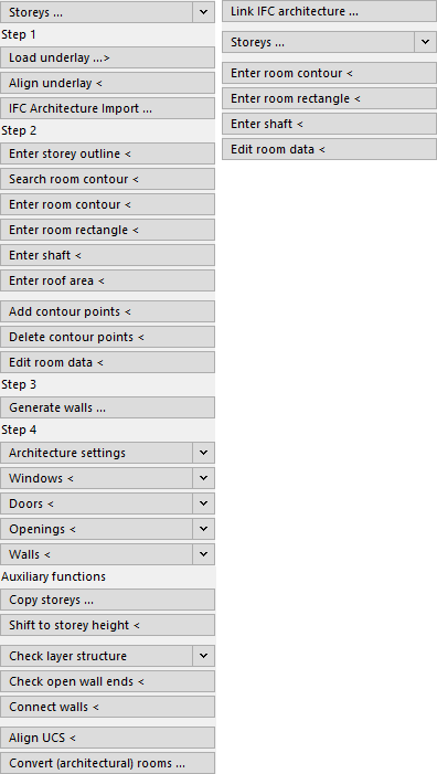
Details on Floor Plan Entry
Information about the command group Floor plan entry in the Building Manager and IFC Building Manager.
The Floor plan entry of the Building Manager is used to create 3D models based on 2D plans and then transfer the building data to LINEAR Building.
The Floor plan entry in the IFC Building Manager is used to create 3D models based on linked IFC architectures and then transfer the building data to LINEAR Building.
You are here:
Link IFC Architecture ...
The Link IFC Architecture command of the IFC Building Manager allows you to link architectures stored in IFC files to your drawing. After selecting the IFC file to be used, you can specify in the dialog Linking IFC Architecture, among other things, which architectural elements are imported from the IFC file. A DWG file with the selected contents is then generated and linked to your drawing.
Storeys ...
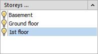
Storeys ... (Building Manager)
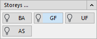
The section Storeys ... displays the existing floors in the Building Manager. Clicking the button Storeys ... opens the dialog Table of storeys. By clicking a light bulb symbol you can turn storeys on or off.
Storeys ... (IFC- Building Manager)
The section Storeys ... displays the storeys imported from IFC Architecture in the IFC Building Manager. For more information about the section, see the help page “Details about storeys ...”.
Load underlay ...>
This command allows you to insert files in DWG or PDF format as well as image files into the drawing. These files are assigned to the current drawing as an external reference.
If you would like to insert several underlays at different heights, you should create a Table of storeys beforehand and set Storeys on upon the other in Drawing type.
If you would like to insert several underlays at the same height next to each other, you should first set the Drawing type to Storeys side by side.
Align underlay <
This command allows you to rotate and scale the underlay to the correct size at the same time. This command is particularly useful to adjust and align scanned plans. Since the horizontal scaling (x-axis) and vertical scaling (y-axis) are queried, even compressed or stretched external references may be straightened again.
IFC Architecture import ...
Opens the Load IFC Architecture dialog where you import an IFC file.
Storey outline/Room contour/Enter room rectangle <
Storey outline/Room contour/Enter room rectangle < (Building Manager)
In order to generate 3D walls on the basis of the 2D template, you will have to define these walls by tracing the storey and room outlines. In the Building Manager, this is done with the commands Enter storey outline and Enter room contour or Enter room rectangle.
Room contour/Enter room rectangle < (IFC Building Manager)
In the IFC Building Manager, you can use these two commands to subsequently add rooms to your drawing that were not assigned in the IFC file. After you have drawn the outline of the room, determine the position of the room label and specify the desired room data in the Room data dialog that opens. If you want to define shafts that are passed to LINEAR Building, use these commands and specify the appropriate settings and name in the Room data dialog.
Search room contour <
In building detection, room information is no longer obtained from the three-dimensional walls, but also from the room contour, among other things. Therefore it is necessary to modify the room contours when walls have been moved or stretched, in order to detect the modified room using the automatic detection.
In the case of a room surrounded by three-dimensional walls, the Search room contour command automatically creates the room contour. Room contours can be stretched or modified as usual by using the grips or by means of the command Add contour points and Delete contour points.
Enter shaft <
You can define shafts using the Enter shaft < command. Shafts do not contain room data and can thus not have a room stamp. They are not taken into account during automatic detection and are not transferred to LINEAR Building. However, the adjacent situation of room components adjacent to such shafts is correctly passed to LINEAR Building.
Automatic detection normally also detects rooms that do not contain openings, provided they are larger than 3m². This means is necessary to detect rooms such as attic or basement rooms, which can be accessed solely via a staircase. In order to avoid detecting any large shaft as a separate room, you may define such as actual shafts explicitly.
Enter roof area <
First define the roof area and then generate the walls. Thereupon, the walls will be adjusted correspondingly and be shortened or chamfered. After having generated the walls, the roof areas may not be deleted. Otherwise the automatic detection and the data transfer to LINEAR Building will not work correctly.
Before starting the Enter roof area command, the course of the roof area should be known. Each sloped plane is a roof area on its own. Thus, a gable roof consists of two separate roof areas.
The first three roof area points require heights that define the slope. For the other points of the roof no heights are required. Therefore make sure you know the heights of the first three definition points.
Add contour points <
You may add contour points to previously traced storey and room outlines or you may delete them in order to incorporate plan modifications into your drawing easily. If the modifications of a room shall be regarded by the automatic detection it is necessary to adjust the room contour, too.
Delete contour points <
You may add contour points to previously traced storey and room outlines or you may delete them in order to incorporate plan modifications into your drawing easily. If the modifications of a room shall be regarded by the automatic detection it is necessary to adjust the room contour, too.
Generate walls ...
As soon as all relevant storey and room outlines and roof areas have been entered, the program may generate 3D walls automatically.
Architecture settings
In the section Architecture settings, you can choose between the 2-points method and the width as numerical value to be applied for the creation of windows, doors, and openings.
Check 2-points method for windows and doors, you can determine the respective width when drawing windows, doors and openings by clicking two points in the drawing. This is useful if you are using a 2D floor plan as a template, for example as an external reference. Then you do not have to adjust the width of windows and doors every time.
In case you prefer to enter the numerical value for the width of windows, doors, and openings yourself, uncheck the box. This may be useful when the same window width occurs frequently or no external reference (underlay) was inserted.
Windows <
In the section Window <, enter the dimensions for width, height and parapet. Click Window < to draw in windows. If you have activated the 2-point method option for windows and doors, you cannot enter the width dimension manually. Click  to measure up a dimension from the drawing.
Doors <
In the Doors < section, enter the dimensions for width, height and doorsill. Click Window < to draw in windows. If you have activated the 2-point method option for windows and doors, you cannot enter the width dimension manually. Activate the Double door checkbox for double doors. Click to measure up a dimension from the drawing.
Openings <
In the section Openings <, enter the dimensions for width, height and parapet. Click Openings < to draw in openings. If you have activated the 2-point method option for windows and doors, you cannot enter the width dimension manually. Click to measure up a dimension from the drawing.
Walls <
In Walls < section, enter the dimensions for thickness and height. Click Walls < to draw in walls. Click to measure up a dimension from the drawing. Activate the Interior walls checkbox for interior walls.
Copy storeys ...
Opens the Copy storeys dialog where you copy already created 3D models to another storey. If the layer key contains the storey abbreviation, the copied components will be placed in the correct storey layer.
Shift to storey height <
Moves an object to another storey. This command is only available for 3D drawings. For example, if you have already inserted the required storey drawings into your drawing on a level next to each other, you can move these objects to the required storey height. If you also use the layer code for storeys in the layer key, the storey codes of the moved elements will be adjusted.
Check layer structure
With this command you can view the layer structure of an object and change it if necessary. This way you can assign walls, windows and doors to another storey if they have been created with wrong layers. The target layers will be recreated if necessary.
Check open wall ends<
Rooms which are not completely enclosed by walls cannot be considered by automatic detection. The Check open wall ends command locates these spots. Open wall ends may be closed by using the command Connect walls.
Connect walls <
It may occasionally occur that generating walls results in open wall ends. Rooms which are not completely enclosed by walls cannot be considered by automatic detection. The Check open wall ends command locates these spots. The gaps created by open wall ends may be filled by using the Connect walls command.
Align UCS <
By using the Align UCS command is you may adjust the current user coordinate system. You may thus apply orthogonally orientated command such as Enter room rectangle and Enter shaft also to rooms which are not rectangular to the drawing surface.
Convert (architectural) rooms ...
This command can be used to convert room objects in AutoCAD Architecture format (AEC Spaces) to LINEAR room contours. Subsequently, these room objects can be used for automatic building detection with LINEAR Building. The conversion is particularly useful when spaces already contain metadata. This is the case when spaces have been created by importing an *.IFC file.
QuickLayer
QuickLayer is a dynamic toolbox that contains a button for each layer in the drawing. These buttons are used to manage the layers. In the dialog QuickLayer, only the buttons of the layers containing objects are available. The dialog QuickLayer can be moved freely on the drawing area or docked to a window edge. To display the QuickLayer, you have to activate the option Activate QuickLayer at program startup on the General tab in the Settings dialog.
Reports
Opens the Reports dialog where the individual error messages are displayed. From there you can display the errors in the drawing.