Details on Building Structure
Information about the Building Structure command group in the Building Manager and the IFC- Building Manager.
The Building Structure command group is used to detect/import building data for transfer to the program LINEAR Building.
You are here:
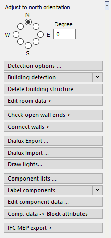
Adjust to north orientation, Degree
Here you may specify the north orientation of your drawing by mouse click or by entering the value in degrees. The data can be taken over by LINEAR Building later. By this means, the orientation of all components, such as external walls and possible windows contained therein is transferred to the PRO file.
Detection options ..., Detection options
Detection options … (Building Manager)
Opens the Options dialog where you can make settings for the building detection . The settings become saved in the drawing. If you would like to change the dimensions for the wall thickness and the openings on a long-term basis, please make these adjustments in the drawing template.
Detection options (IFC Building Manager)
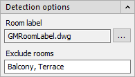
Room label
Displays the room labeling file that is used. Click  to select an labeling file.
Exclude rooms
Specifies which rooms are not to be included in the detection. Enter the names of the rooms used in the Room data to exclude rooms from the building detection. To exclude multiple rooms, separate the room names with commas. Rooms excluded from the building detection will not be included in the data transfer to LINEAR Building. Room components of other rooms that are adjacent to excluded rooms are transferred to LINEAR Building as adjacent to outside.
Building detection
With the building detection you can import building structures that have been created with the Building Manager or IFC Building Manager assistant with one mouse click and then transfer the data into the program LINEAR Building. After executing the building detection, the building structure is displayed in the section Building detection in form of a tree structure. Since the detection is carried out independently of the program LINEAR Building, you have the option of checking whether the rooms have been correctly recognized and, if necessary, making changes to the building structure without causing changes in LINEAR Building. The transfer of the data then takes place from LINEAR Building.
Highlight selection
Enabled: The element selected in the building structure is highlighted in color in the drawing.
Delete building structure
Deletes existing building structure from the section Building detection. This may be useful, if the rooms have not been detected correctly and you have changed the drawing subsequently after the first automatic detection. Before you start the automatic detection again, delete the old building structure by clicking Delete building structure.
Edit room data <
With this command you can edit room data like room name, room number or temperatures afterwards. The room label may be exchanged by another block, if required. The room label is exchanged after closing the dialog by OK.
If a room label is missing, it can be added using the command Edit room data <. In this case, click the room contour instead of a label.
Check open wall ends<
Rooms which are not completely enclosed by walls cannot be considered by automatic detection. The Check open wall ends command locates these spots. Open wall ends may be closed by using the command Connect walls.
Connect walls <
It may occasionally occur that generating walls results in open wall ends. Rooms which are not completely enclosed by walls cannot be considered by automatic detection. The Check open wall ends command locates these spots. The gaps created by open wall ends may be filled by using the Connect walls command.
Dialux Export ...
Once the automatic detection of a 3D building was made, you may transfer the room data to DIALux software for further planning.
Dialux Import ...
STF-files that have been modified by DIALux software can be imported into the CAD drawing. The lights added with DIALux can be drawn in afterwards.
Draw lights...
Once a *.STF file has been modified with DIALux software and imported into the drawing, you may use this command to have the planned lights and lamps drawn as CAD lights.
Component lists ...
Opens the Component lists dialog. Component lists process component data for displaying and outputting data in tabular form, for adding/changing data directly, and for exporting/importing data using Excel for external supplementation or change. By importing you can, for example, import room log books into building models.
Label components
In the Label components section, you find the commands and settings for labeling components. Labels that you have created from component lists are also available in this section.
Edit component data --- - Central metadata administration
This command allows you to read out the attributes of individual components, edit them or add new attributes. This is possible for simple blocks as well as LINEAR objects like 3D pipes or 3D air ducts.
This metadata can be used to label the components or for the export commands IFC TGA-Export < and PCF-Export <.
Component data → Block attributes
Via this command, a proxy-free export is performed. It serves to convert the component data assigned with the Edit component data... command into block attributes. (see Edit component data ...). By this means, the drawing may be analyzed, e.g. by a facility management software. This process is not reversible. The program will thus create a new file for which you may freely define a name and a storage location.
IFC MEP-Export<
During LINEAR the IFC Export, LINEAR objects of the modules Design 3D Pipe&Power, Design 3D Ventilation, panel heating/cooling systems including all system and calculation data as well as the architecture (AEC walls) are detected. Besides the 3D model also the corresponding metadata is exported. When opening an exported file, not only the model is displayed, but also the manufacturer data, the material, dimension and other characteristics are indicated in the properties dialog of the component. Components deriving from the modules Design 3D Pipe&Power and Design 3D Ventilation will correctly be classified by the export process. Other components (such as CAD blocks, walls, windows, doors, etc.) will also be exported on demand, but export process will only consider the 3D model.
QuickLayer
QuickLayer is a dynamic toolbox that contains a button for each layer in the drawing. These buttons are used to manage the layers. In the dialog QuickLayer, only the buttons of the layers containing objects are available. The dialog QuickLayer can be moved freely on the drawing area or docked to a window edge. To display the QuickLayer, you have to activate the option Activate QuickLayer at program startup on the General tab in the Configuration dialog.
Reports
Opens the Reports dialog where the individual error messages are displayed. From there you can display the errors in the drawing.