Details on Technical Data for Flow Dividers
Information on the technical data dialog for flow dividers.
The flow divider prevents, in combination with a closed circular pipe, the stagnation of the water within this closed circular pipe.
For the calculation it does not matter in which direction the flow divider is inserted. For a graphically correct presentation the symbol is inserted in flow direction in the ascending pipe. At the top end of the flow divider a circular pipe closure (with layer closed circular pipe) is drawn, at the bottom end of the flow divider a potable water pipe (cold or hot water pipe) is drawn. The outlet valves are connected to the circular pipe closure and to the potable water pipe.
If water is tapped above the flow divider, this will cause a negative pressure in the constricted part of the component. This will cause a differential pressure above the closed circular pipe. Thus a hygienic flow within the closed circular pipe is generated.
The flow direction for the calculation is determined by the circular pipe closure.
You are here:
Name
Specifies the name of the component. You can modify the name. Clicking  restores the default setting.
Product selection
Depending on the product selection, the range shown below varies. Available for selection:
-
Manufacturer product - VDI 3805- Domain: Valve from VDI 3805 sheet 17
-
Manufacturer product - product data - Domain: Valve from product data
-
Manual entry - Bereich: Manual entry
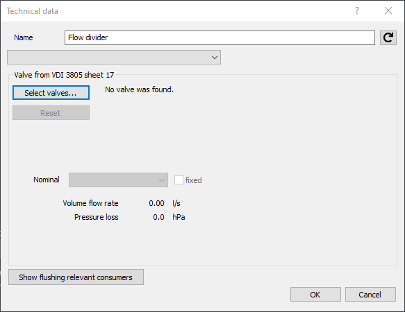
Valve from VDI 3805 sheet 17
This is the standard setting for the flow divider. If no manufacturer product is selected, a corresponding error message is output in the calculation.
Select valve...: Opens the dialog Select Valve Series in which you can select a manufacturer-specific flow divider. The selected flow divider and its properties are included in the calculation.
Reset: Resets the selection of a manufacturer-specific flow divider.
Nominal diameter/fix: Drop-down list with the available nominal diameters of the selected flow divider. Once a dimension is selected, the option is fixed The selected dimension is then used for the calculation.
Volume flow rate/Pressure loss: Shows the calculated flow rate and pressure drop for the selected flow divider.
Show flush relevant consumers: Depending on the selected product data, you can display the relevant consumer for the flow divider in the model.
Valve from product data
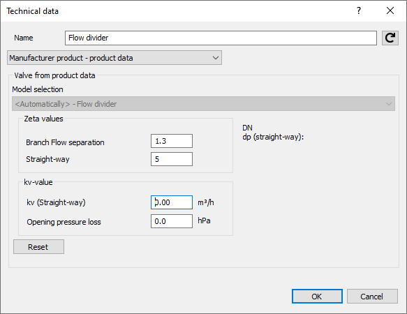
Model selection: Depending on the selected product data and the set pipe system, a model is automatically assigned. Figure 640 or 650 is automatically recognized as Manually and the stored values are accepted.
Zeta value: The Zeta values are suggested by the program. Using a flow divider of a special manufacturer, these values are fixed, whereas Zeta values of neutral components can be adjusted.
kv-value: If values are stored for an automatically recognized model, they are displayed here. If no values are available, they can be entered manually.
Reset: Resets all edited input fields back to default values.
Manual entry

Model selection: Displays the automatically determined model.
Zeta values
Activated: The pressure loss of the flow divider is determined based on the values for Branch flow separation and Flow through.
kv-value
Activated: The pressure loss of the flow divider is determined based on the kv-value of the flow through. The Opening pressure loss is the minimum pressure loss of the component in the flow through.
Reset: Resets all edited input fields back to default values.