Details on Basic Elements
Information about the Basic elements section.
You are here:
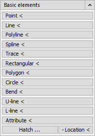
In the multifunction board (MFB), the basic drawing elements Point, Line, Polyline, Spline, Trace, Rectangular, Polygon, Circle, Bend, Attribute, Hatch and Location (for defining the view order) are arranged via the buttons of the same name in the Basic elements section. These are the commands already known from the CAD program. See the CAD Help for more details on these commands. Furthermore, in this command arrangement you will find the LINEAR -commands U-line < and L-line <.
| Command | Description |
|---|---|
| Point < | Draw point Use this command to set the position of a point. |
| Line < | Draw line This command allows you to draw a line between a free and a predefined start/end point. |
| Polyline < | Draw polyline This command can be used to draw a so-called polyline over multiple free or predefined interpolation points. |
| Spline < | Draw spline This command can be used to draw a point sequence of supported curves (square or cubic spline). |
| Trace < | Draw trace With this command a trace can be drawn by an additional width factor and free/preselected points. |
| Rectangular < | Draw rectangles This command draws rectangles after entering two corner points, which can be inserted into the drawing with any rotation angle. |
| Polygon < | Draw polygon With this command you draw a polygon by either drawing it into or around an imaginary circle. Alternatively, you can set the endpoints of the first side of the polygon. |
| Circle < | Draw circle With this command you draw a circle which is drawn around a center point or which is given a predefined radius. Circles can be created in different ways, e.g. with the diameter and two points or with the circumference of the circle defined by three points. |
| Bend < | Draw bend This command allows you to span a bend segment over two arbitrary or specified support points. |
| U-line < | Draw U-shaped lines With this command you can draw U-shaped lines, e.g. bridges in the electrical field, very easily. The lines run parallel to the X or Y direction of the current coordinate system and the U is open upwards or downwards. Specification of points: 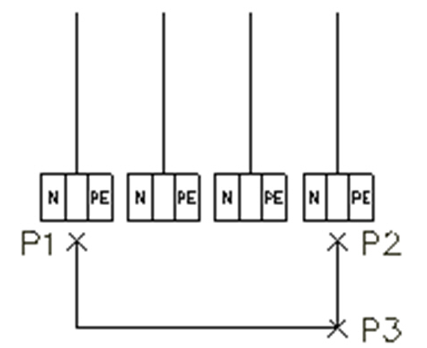 Result: 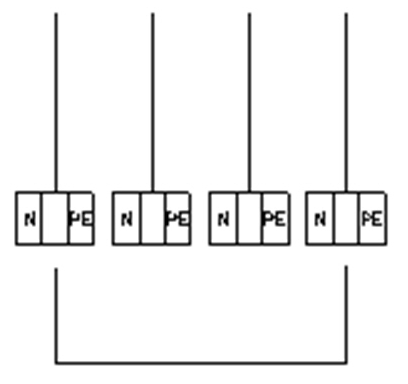 |
| L-line < | Create L-shaped line automatically With this command you can draw L-shaped lines as easily as simple lines or polylines. You specify a starting point from which you want to draw a right angle (L-line). The two legs of the angle are arranged horizontally and vertically, respectively. 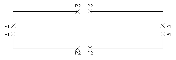 |
| Attribute < | Attribute definition This command allows you to define attributes. For more information, see the CAD Help. |
| Hatch ... | Draw hatch Select a hatch type and insert the hatch into your drawing. For more information, see the CAD Help. |
| - Location < | Set view location The - Location < button allows you to specify the order in which drawing elements lie on top of each other. For example, you can place a hatch at the very bottom (Below option) so that texts do not lie behind the hatch and are thus difficult to see. |