Details on Settings (Display)
Information about the Settings dialog of the Display tab.
You can use the Settings palette to make general presettings for editing and displaying drawings. The settings for line type, line weight and line color of center lines are used for displaying tube axes of 2D pipe construction and 2D air duct construction.
You are here:
Units
Clicking the button opens the CAD dialog Drawing units. Type and precision of length and angle units can be defined in this dialog. For more information, see the CAD Help.
Selection modes/Grips
Clicking the button opens the Selection tab in the CAD dialog Options. Specify in which mode the selection of objects should be made, e.g. objects should be selected before or after selecting a command. Activate the grips ( show grips ) and select the grip colors. Grips within blocks can also be shown. For more information, see the CAD Help.
Point style
Clicking the button opens the CAD dialog Point style. Set the display of the points in the drawing. The display type does not affect the plot. Points are always plotted as a dot. For more information, see the CAD Help.
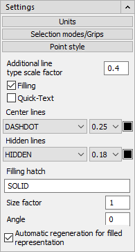
Additional line type scale factor
The additional line type factor defines the scaling of line and dot sequences in LINEAR CAD, i.e. how wide the line and gap should be displayed for a dashed line. The additional line type factor achieves that the LINEAR line types can optimally be displayed in the model space and the paper space. It is preset with a value of 0.4 and can be set to three digits after the comma.
In the LINEAR Configuration on the General tab, you can set if the line types should be optimally displayed in model space (for drawing) or in the paper space (for plotting). This affects the calculation of the global LT factor and thus the display of line types. The additional line type LT factor remains unchanged. In model range optimization, the global LT factor is calculated from the additional LT factor and the scale.
If you, e.g., would like to display the dashing of the lines more finely, you can affect this by changing the additional line type factors. For example, if you enter a smaller additional line type factor, the line will be displayed with much finer dashes.
Set the view to which the LT-factor should be applied: the model space (for drawing) or the layout (for plotting). You can access the LINEAR Configuration using the button at the bottom right in the LINEAR User Interface.
On the General tab, set the line type factors to be optimized for the selected area (model or layout).
Filling
Filled surfaces such as solids, thick polylines or bands, are only shown as filled when this option is activated by checking the checkbox. Filling can be deactivated for elements that are inserted from the symbol toolbar. This only works when a medium, for e.g. Supply air single treated is selected when the elements are placed.
Quick-Text
The text display is limited to bordered rectangles when this option is activated. This way you save time when regenerating drawings with large amounts of complex text elements (e.g., TrueType fonts). Used as placeholders, rectangles are faster to process than the pixels for a gothic font.
Center lines
Specify which line type the center lines of pipes or spiral ducts of the 2D Piping and 2D Ventilation (Round Duct) functions should have. Set the color of the center line in the field to the right. These settings also affect the elements which are set in the symbol toolbar, for e.g. as elbows, branch saddles, sound absorbers, branches, T-/cross pieces, reducing pieces, flexible pipe and pipe. Lines which are created using the Systems of axes command also use these settings.
Hidden lines
As with center lines, the line type and the color can be set for hidden lines on 2D Pipes.
Filling hatch, Size factor, Angle
Indicate which filling hatch should be used. In addition, indicate which size factor and angle should be used for the hatch. The filling hatch is used for filled 2D ducts for example.
Automatic regeneration for filled representation
In case of filled display of, e.g., 2D Air ducts, it might happen that the drawing sequence is not displayed correctly and the drawing has to be regenerated first. The duct drawn last is always above the ducts drawn before. When the automatic regeneration option is activated the current view will automatically be regenerated after finishing the duct command. Thus, the correct drawing sequence is shown. In large and complex drawings this step may take some time. In these cases it is recommended to untick the automatic regeneration option and carry out the regeneration manually after having finished the duct construction.