Details on Symbols
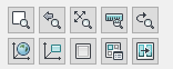
Information about the display control icons in the upper part of the Display tab.
You are here:
Zoom window  :
:
After clicking this button you will define a window for the zoom section with two opposite corner points.
Zoom previous 
This restores the last zoom section used.
Zoom extents 
Zoom to the drawing extents to display the whole drawing.
Zoom to scale 
Use this function to display a drawing in one of the available scales. This zoom function is only available if you have selected a layout tab at the bottom left of the area selection and the drawing is displayed in a viewport.
Rotary zoom 
In a slope arrangement of the components (for example floor plan) use this function to simultaneously zoom and rotate the view to the horizontal position. This corresponds exactly to the oblique stretching of a drawing on the drawing board in order to be able to work horizontally and vertically again.
Click the Rotary zoom button and set the first corner point (Undo/<first corner>) of the zoom window in your drawing. Determine the rotation angle. Drag the area of the zoom window with the mouse and set the endpoint.
User coordinate system to WORLD 
Use this function to adjust the User coordinate system (UCS) of your CAD program to the world setting. The World coordinate system(WCS) cannot be modified. By contrast, the UCS can be freely defined in height and orientation. The reference to the world coordinate system provides unique coordinates and is oriented so that the positive area of the x-axis points east and the positive area of the y-axis points north. The positive area of the Z axis is the height axis. Editing the drawing with the UCS on world corresponds to the normal floor plan editing from the top view.
User coordinate system to VIEW 
A user coordinate system is activated which fits to the current view. Since complete 3D editing in the top view alone is hardly possible, you can align your coordinate system to any adjustable view, e.g. to draw in or label objects in a front view of your 3D drawing.
For example, if you would like to label your 3D drawn pipe network in an isometric view, proceed as follows: Set the designated isometry, set the coordinate system to the current view and label the pipe network the same way as in the floor plan.
Single viewport 
It is often helpful to divide the drawing area into several viewports, e.g. to see a top view in one window and a front view in another window at the same time. This gives you the possibility to visually check the level, for example, during entry. If you did this with the divided viewport command and would like to switch back to displaying a single viewport, use this command.
Divided viewports 
It is often helpful to divide the drawing area into several viewports, e.g. to see a top view in one window and a front view in another window at the same time. With this division you have visual control during entry, e.g. when entering the height level.
This button opens the Viewport CAD dialog where you can select one of multiple predefined viewport combinations or create your own combination. The viewport combinations you create here can be saved under a name of your choice. All settings are saved, e.g. the current view, the visual style, or activated sections.
Copy viewport setting 
Use this button to copy the settings of a viewport in the layout area. You can then assign the settings of the source viewport to a target viewport. This command is only available in the layout view.
For example, you selected a layout tab with two viewports, where you would like the left viewport to be the source window whose settings will be copied and pasted into the right viewport. Proceed as follows:
First, make sure that the model space of the layout view is activated. Click the copy viewport setting button. Please consider the prompts in the command line. Click into the target viewport and confirm with Enter. Click into the target viewport and confirm with Enter. In the command line you are prompted to enter if the sectional planes shall be switched off, if necessary. Enter Yes or No and confirm with Enter. The settings are then applied.