Details on System Preselection
Information on the System preselection section of the Panel heating/Panel cooling tab.
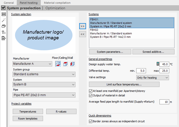
In the System preselection, select a desired panel heating systems in the System selection section and add the selection to your project. Added systems are listed in the Systems section, where their System parameters... and system-dependent Screed additives... can also be set. In addition, in the System preselection section, General default settings, settings for the Project variables and settings for Quick dimensioning can be defined.
You are here:
System selection
In the System selection area, select the manufacturer, the system group, the system and pipe type to be dimensioned to add them to the preselection of your project.
Use the Floor/ceiling/wall buttons to define the position of the system in the room.
Not every manufacturer offers ceiling and wall systems.
Editing the preselection of systems
Use the button  to transfer the selected system to the Systems field. The system is now in the preselection and is available for dimensioning in the current project. During the project editing you can add additional systems for preselection.
Use this button  to remove a selected system from the preselection in the Systems field. This is only possible if the system is not used in the project. If a system that is no longer in use cannot be removed, click one of the message buttons
  in the symbol bar. The project will be recalculated and you can then remove systems that are no longer used.
System
Displays the systems assigned to the project and allows settings to be made for the system parameters and screed additives of the respective system. If the Screed additives... button is deactivated, there are no screed additives for the selected system.
Project Variables
The buttons Temperatures, R-Values and Room templates open the corresponding dialogs in which the master tables belonging to the variables can be edited.
General default settings
Determines the default settings for designing all of the project’s systems.
Dimensioning supply water temperature
Defines the design supply water temperature to be used as the basis for calculation.
The  button is displayed only for panel heating systems and opens the Supply water temperature design dialog, where the design supply water temperature can be calculated using all relevant parameters.
Min. differential temperature
Defines the desired minimum differential temperature between supply and return water temperature.
The room temperature is automatically considered as the minimum possible return water temperature and will not fall below it.
Max. differential temperature
Defines the desired maximum differential temperature between supply and return water temperature.
Valve setting
Defines the calculation case the valve setting is shown for. Displayed are only those options for which the manufacturer provides the system.
| Valve setting | Description |
|---|---|
| Only for heating | The optimum balancing of the required throttle resistances of the heating circuits via the control valves/flow rate controllers is only carried out for the heating case. The optimal operation for cooling in summer cannot be guaranteed. This may lead to restrictions in comfort. |
| Mixed mode | The optimal balancing of the required throttle resistances of the heating circuits via the control valves/flow rate controllers is achieved as an optimal combination between heating and cooling. Each valve is checked for the required setting value for the heating case as well as for the cooling case. The valve setting with the lowest pressure loss is assigned to the valve. It is guaranteed that in normal projects there are no comfort restrictions. This method is based on the assumption that the room controllers, in connection with the actuators, ensure the necessary residual throttle resistances for a hydraulically balanced pipe network, regardless of the season. Note: In mixed mode the system is not hydraulically balanced. The required power supply has to be ensured by the closed loop control system. |
| Mixed-M. prior Heating | The optimal balancing of the required throttle resistances of the circuits via the control valves/flow rate controllers is carried out as mixed mode with a preference for the heating case. Note: In mixed mode the system is not hydraulically balanced. The required power supply has to be ensured by the closed loop control system. |
| Mixed-M. prior Cooling | The optimal balancing of the required throttle resistances of the circuits via the control valves/flow rate controllers is carried out as mixed mode with a preference for the cooling case. case. Note: In mixed mode the system is not hydraulically balanced. The required power supply has to be ensured by the closed loop control system. |
Limit surface temperatures...
The button opens the dialog Limit Surface Temperatures, in which the maximum permitted surface temperatures for the dimensioning of surfaces with systems are defined.
At least one manifold per apartment/storey
Activated: A separate manifold is created automatically for each new apartment and each new floor.
Deactivated: A new manifold is created if the maximum number of circuits is exceeded in the manifold used.
Identifying material in detail
Activated: A detailed listing of all components in the parts list is provided.
Deactivated: In their parts lists, some manufacturers combine components into material packages.
Average feed pipe length to manifold (supply+ return)
Defines the average length of the feed pipes from the heating circuit to the manifold at initial design. Add the pipe lengths of supply and return water pipe to the manifold.
Usually the heating circuits are dimensioned first, followed by the calculation of the feed pipe lengths to the manifold. The calculated values are entered in the room components table. When using the actual feed pipe lengths, the maximum pressure loss or the maximum circuit length may be exceeded. This can be avoided by specifying the average feed pipe length.
Quick dimensioning
Defines the setting for border zones in quick dimensioning.
Border zones always as independent circles
Enabled: During quick dimensioning, the border zones are automatically created as independent circles with their own manifold connection.
Disabled: The border zones are created during the quick dimensioning as row-integrated border zones in the circles of the occupied zones.
Toolbar of the system preselection
Additional functions are available in the function bar between the building structure and the system preselection. The width of the toolbar is variable. This allows you to make the designations to the right of the buttons visible.
U-value calculation
 : Opens the U-value calculation of system components in the master tables.
Optimize
 : Executes an optimization of the dimensioning. This is useful if parameters of the dimensioning have been changed and a complete redimensioning is not desired.
An exception is the optimization of the number of circuits: It corresponds to a redimensioning of the panel system in the room.
The following variants are available for selection:
-
Differential temperature optimizing (DT)
Optimizes the dimensioning by adjusting the differential temperature.
The laying spacing and the defined circuits remain unchanged.
-
Laying spacing optimising (LS + DT)
Optimizes the dimensioning by adjusting the laying spacing and differential temperature.
The defined circuits remain unchanged.
-
Circuit quantity optimizing (CQ + LS + DT)Laying spacing optimising (LS + DT)
Optimizes the dimensioning by adapting all parts of the active situation.
All individual specifications are replaced if possible.
Create labels
 : Opens the program liNEtikett, which allows you to create and print labels for the inscription of manifolds and manifolds outlets. The prerequisite for this is that the dimensioning of the panel system has already been executed.
Additional material
 : Opens a catalog for additional material selection of the manufacturer. Additional materials from manufacturers whose systems are in the preselection are shown.
Imports projects dimensioned by means of the online quick dimensioning
 : Enables the import of projects from online quick dimensioning in WEBPRO format. After the import the project can be edited further.