Details on System Parameter
Information on the System parameter dialog.
You are here:
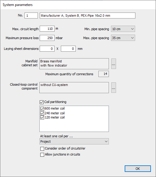
System parameters
In the System Parameters dialog, project-specific system parameters can be individually adjusted and defined. The selection of options depends on the manufacturer and system and can therefore vary.
As system parameters of a selected system, the Maximum circuit length, the Maximum pressure loss of a circuit and, if necessary, limitations for minimum and maximum laying spacings (Pipe distance minimum/Pipe distance maximum) can be defined.
No.
Defines the number and the name of the selected system.
Maximum circuit length
If you would like to limit the length of the pipe for a circuit, you can specify the Maximum circuit length. Please pay attention to the maximum values specified by the manufacturer. These manufacturer's values serve as limits for the dimensioning of the circuits and cannot be exceeded even by specifying higher user limits. You should therefore not exceed these upper limits, in order to have room for adjustments later.
Maximum pressure loss
Detects the highest pressure drop in the pipe for a circuit. Please pay attention to the maximum values specified by the manufacturer. These manufacturer's values serve as limits for the dimensioning of the circuits and cannot be exceeded even by specifying higher user limits. You should therefore not exceed these upper limits, in order to have room for adjustments later.
Minimum pipe spacing/Maximum pipe spacing
Limits the minimum and maximum pipe spacing available for the calculation. The selection lists only show the pipe spacing values available for the respective system.
Laying sheet dimensions
Laying sheet dimensions are used for the graphic representation of the systems in the CAD drawing or CAD model. They are editable as long as no manufacturer's specifications are defined. Otherwise, the manufacturer's specifications for the selected system are shown and the input fields are locked.
Manifold cabinet set
Depending on the manufacturer and the selected system, suitable manifold cabinet sets are supplied. The standard accessories are shown.
 : Opens the Select a Manifold cabinet set dialog, which allows you to select Manifold cabinet sets and edit the accessories.
Maximum quantity of connections
Shows the maximum number of connectors of the manifolds of the selected system. The maximum number of connectors a manifold has depends on the manufacturer and cannot be changed.
Closed-loop control component
Depending on the manufacturer and the selected system, suitable control component are supplied. The standard accessories are shown.
: The button opens the Select a Single room closed-loop control system dialog, which allows you to select Room control systems and to edit accessories.
Coil partitioning
Some manufacturers offer their systems on coils. In these cases, the Coil partitioning checkbox and the other setting options are activated. The available coil sizes of the system are shown. You can then specify which coils are used for the dimensioning. For systems that are not offered on coils, this section is deactivated.
At least one coil per...
Determines if a new coil should be commenced for each Apartment or Storey. If not, and you would like to minimize waste, select Project.
Consider order of circuits
Activated: The individual circuits are wound off the respective coils by circuit number, until the coil is exhausted. The next coil follows. This means that less attention has to be paid to the plan when installing the pipes. However, there may be more waste cut as the coils are not adjusted to the length of the pipes in the circle.
Deactivated: The coils are distributed ideally on the individual circuits, regardless of circuit number. It may be that the laying starts at circuit 3 and is followed by circuit 1, because both circuits together require the amount of material of one coil. This requires more attention during installation and a precise plan. There is less waste cut. Which circuits are executed with which coils is output in the label of the manifold. The assignment of the coils to the respective circuits can also be seen in the printout of the Assembly list per manifold.
Allow junctions in circuits
Activated: Each circuit from the manifold to the room and back again is executed in one piece. The remains of the individual coils are not used; more material will be needed.
Deactivated: A circuit can be made up of several portions from different coils. This reduces waste cut and saves material. However, additional pipe couplings are required for installation.