Details on Advanced Edit Commands
Information about the Advanced edit commands section on the Edit tab.
You are here:
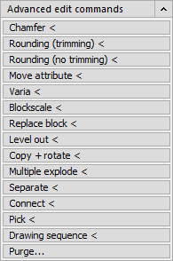
In this section a multitude of commands for editing objects is available.
Chamfer <
This command connects one line to another with a chamfer. The pipe connected to is known as the main line. The connecting pipe is referred to as the connecting line. When chamfering, the connecting line is cropped or extended as required, the main line remains as it is. The chamfer distance is adjustable. The direction of the chamfer is controlled via the point at which the main line is clicked, in relation to the connecting line.
Rounding (trimming) <
This command rounds off the edges of two objects with an elbow in a freely selectable radius. During this process, you can set whether the object to be rounded is to be fitted to the elbow (trimmed or extended as required) or whether it is to be kept as is. The rounding command also rounds off the edges of 3D objects.
If the two lines to be rounded off are located on the same layer, the program creates the rounding line on this layer. Otherwise the rounding line is created on the current layer. The same applies to the filing color, the line weight and the line type.
R option (Radius): The default radius is 0 (zero). This lengthens or shortens the two lines to a common point of intersection without entering an elbow. The same can be achieved by clicking the object to be rounded off and holding down the Shift key. (See command line: Select objects with the Shift key held down to use a corner )
The T option (Trim) determines whether the objects to be rounded off are to be adapted at the elbow ends or not. If the crop option is activated the objects are cropped or extended as required.
The P option (Polyline) enables rounding off of all segments of a polyline in a single process. To do this, select two segments of a polyline and all segments of the polyline are rounded off.
Rounding (no trimming) <
This command connects a line to another with a circular elbow. The pipe you connect to is the main line. The connecting pipe is referred to as the connecting line. The radius of the circular elbow can be defined. The direction of the circular to control via the point at which the main line is clicked.
If you, for example, click the main line at a position above the connecting line, and the circular elbow is drawn upwards and vice versa.
Move attribute <
This command serves to position attributes of drawn blocks. This can then be used, independently of the position of the actual block, to modify every attribute individually with start points and rotations.
Attributes are, for example, the labels and numbering of connection clamps in the circuit diagram or the utility name of a switch.
Varia <
This command increases or decreases the size of the selected objects equally on the X, Y and Z axes starting from the base point. The change in size depends on the scaling factor.
Blockscale <
This command scales the size of selected blocks in all directions. It is particularly suitable for scaling LINEAR symbols in your drawing when these are already connected to pipes. When executing the BlockVaria command, these pipes are tracked. This means that when you, for example, want to reduce the size of all symbols on your drawing by half, all pipes will still be correctly connected even after the reduction.
Replace block <
This function allows you very easily replace, for example, all wash stand blocks for LINEAR CAD symbols that you can subsequently use in the LINEAR Analyse programs.
Level out <
This command is used to set the Z coordinate values of all selected drawing elements to a new common Z value.
Copy + rotate <
This command combines the COPY and ROTATE commands. The elements are simultaneously copied and rotated. This is always reasonable if you require drawing elements (e.g. blocks, symbols) within a drawing again but in another orientation (e.g. a straight way valve in a horizontal and vertical installation position).
Multiple explode <
Use this command to resolve nested block definitions in a single step. When resolving objects, the type of the object determines the properties that can be changed, such as layer type, line weight and color. For blocks which contain attributes, the attribute values are deleted and the attribute definitions are displayed.
Separate <
This command interrupts the selected element at a point. A line can then, for example, be divided into two lines. This corresponds to the CAD BREAK command for a point.
Connect <
This command connects lines in various different ways. This will depend on the positions of the two lines to each other.
If both lines are in alignment, one single line is created.
If the lines are not aligned and the Trim mode is not activated , the second line is connected to the first line (or the extension thereof). If these pipes are defined with a chamfer in the media table, a chamfer is created when the line is connected (see the Chamfer command).
If the lines are not aligned and the Trim mode is activated , both lines are lead to their common intersection point (by lengthening or shortening). If a chamfer has been defined in the media table for this medium the connection will be carried out with a chamfer.
Pick <
Use this command to separate one line into two and move the new two common endpoints. The picking command may also be used for polylines and arcs.
This command is perfectly suited, for example, to "pull" a previously continuous line, e.g. around a connecting pipe, by creating two additional corner points.
Drawing sequence <
Usually objects are displayed in the sequence in which they were drawn. The drawing sequence command changes the display sequence of the objects by, for example, bringing one object in front of another one.
Changing the sequence ensures that the objects are displayed and plotted correctly when several objects overlap. This is required, e.g., when an inserted pixel image lies on top of existing objects and covers them.
Purge... <
The CAD dialog box Purge lists drawing elements that have not been used in the drawing. These are not referenced objects (drawing elements without a relationship to other drawing objects). Drawing elements that have not been used, can be removed individually as a block or all at once.