Details on Plate Heat Exchanger (Generator)
Information about the Plate heat exchanger dialog in the Generators section of the 3D Pipe Construction.
You are here:
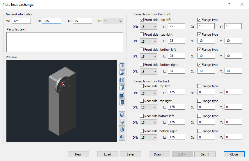
General information
B / H / T: Enter the desired width, height and depth for the plate heat exchanger in these fields.
PN: Select the required pressure stage from the drop-down list.
Preview
When you have completed the dimensions in the General information section, a 3D model to scale is generated in the preview window. You can rotate the model by grabbing it at any position with the left mouse button pressed and moving the mouse. You can zoom the model in or out in the preview with the mouse wheel. If you keep the mouse wheel pressed, you can move the view of the model.
The view in the preview can also be controlled using the buttons to the right of the window. The viewing side that you can set using the buttons is marked in dark blue on the button icon.
Connections from the front / back
Front side, Rear side, left, right, top, bottom – activated: The position is provided with a connector according to the presettings.
DN: Use the drop-down list to set the nominal size for the individual connections. If you set the nominal size for the first of the four ports, the setting will be adopted for the remaining three. The setting for the ports can then be adjusted individually for the connections.
L: Use the drop-down list to set the length for the individual connections. When you set the length for the first of the four connections, the setting is applied to the remaining three. The setting for the ports can then be adjusted individually for the connections.
Flange type – activated: The connections are created as flange type. If you enable this option for the first of the four connections, the setting will be applied to the remaining three. The setting for the connections can then be adjusted individually.
X / Y: Use the two fields to set the offset of the connectors on the X and Y coordinates with positive or negative values. If you set the values for the first of the four connections, the value for the remaining three will be applied. The values for the connections can then be adjusted individually.
New: This button removes the current data for a plate heat exchanger and allows you to create a new one.
Load: Load the data of a stored plate heat exchanger.
Save: Save the displayed data of a plate heat exchanger under a name of your choice.
Draw <: Use this button to place the current plate heat exchanger into the drawing area. The starting position is queried.
Edit <: With this button you can edit a plate heat exchanger located on the drawing area. Proceed as follows: Pick the plate heat exchanger from the drawing area, change the data, and then click Edit < to transfer the changed data to plate heat exchangers in the drawing area.
Get <: Use this button to get the data of a plate heat exchanger located on the drawing area into the Plate heat exchanger dialog. In the dialog you can change the data and transfer it to the plate heat exchanger on the drawing area by clicking Edit <.
Save the newly created or modified plate heat exchanger if you want to continue using it. When closing the Plate heat exchanger dialog, the current data is not saved. After reopening, the plate heat exchanger window is empty.