Details on Pipe Construction (2D Piping)
Information about the section Pipe construction in 2D Piping.
With this command you can draw pipes as easily as lines. When drawing, you define the support points along the pipe axis and the pipes are generated automatically.
The insulation is co-generated if required. The insulation thickness can be selected freely. The text function automatically recognizes dimensions of existing components.
The program can be automatically set to the nominal size of existing components in order to continue drawing in the same size.
You are here:
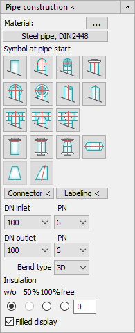
Pipe construction <: Clicking this button will start the pipe construction command.
Material: Click on  to open the Load pipe material dialog, where you can select and load an RMD file with the required material in the file explorer. The currently loaded material is displayed on the button below, e.g. steel pipe, DIN2448. If you click the button with the material specification, the Material info window for the selected material opens.
All flanges, bends, caps, reducers, transition pieces, T- pieces and seamless steel pipes from DN15 to DN3600 are defined in the material file.
Symbol at pipe start:: Use the buttons shown to start and stop the drawing command for pipes. Select the initial component from the graphic symbols, and then draw the pipe by specifying the corner points. After entering the end point, press Enter to return to the dialog where you can then select an end component for the last point entered.
Connector <: To query the dimension of an already drawn pipe from the drawing, click this button and either select a component in the drawing (e.g. flange, cap, transition piece or similar) or click the axis of a straight pipe.
In the first case, the program immediately returns to the dialog and displays the detected pressure levels and dimensions. In the second case, the program tries to find a pipe edge by itself. If this is not successful, the program asks for a pipe edge which you must show (object snap perpendicular is set automatically).
The program then searches for a suitable pipe dimension in the current material file and returns to the dialog with this setting.
Labeling <: Click this button and then click a component in the drawing to label it.
DN inlet / DN outlet: Select the desired pressure rating (PN) and dimension (DN) from the list in the Input field. These entries are automatically transferred to the Outlet field. If a different pressure rating or dimension is required at the outlet (e.g. for a reducing socket), this value can be changed.
Bend type: The bend radii defined in the material file (e.g. 2D, 3D or 5D) are displayed in a list. Select the desired bend type here before drawing.
Insulation: Insulation: In the material files, the insulation thicknesses of 50% or 100% can also be set for each pipe dimension using the corresponding buttons. With the radio button w/o (without) or by entering a free insulation thickness of 0 you suppress the drawing of an insulation. The insulation is placed on its own layer. The layer name is derived from the current medium with the insulation component. The elements, their color and line type depend on the layer and can be set in that layer.
Filled display: If this option is enabled, the next lines will be filled with the media color and the pipe edges will be highlighted in black. If the option is disabled, the pipes are displayed with the media color and do not show any filling.