Details on the Calculation Dialog for Circulation Systems
Information on the Circulation dialog.
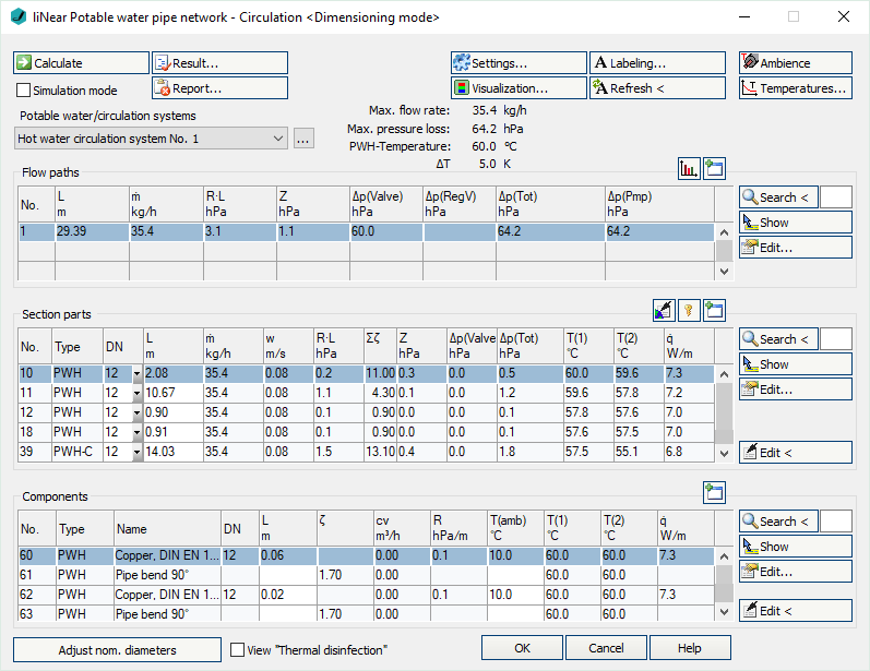
The calculation dialog shows an overview of the detected pipe circulation systems and contains all functions necessary for the calculation.
You are here:
Functions for the calculation
The functions in the upper part of the calculation dialog pertain to the entire pipe network.
| Element | Meaning |
|---|---|
 Calculate | Initiate the calculation of the pipe network after having made changes to see current calculation results. |
| Simulation mode | Activated: Switches to simulation mode and initiates the calculation. Nominal pipe sizes, pump- and valve settings for the selected circulation system are fixed during simulation mode. The resulting mass flow rates and temperatures are then analyzed on the basis of these data. Deactivated: Switches to dimensioning mode. Nominal pipe sizes, pump- and valve settings are unfixed. |
 Result... | Displays additional information regarding the pipe network and an overview of the calculation results, which also are part of the printouts. |
 Report... | Displays an overview of notes and errors that occurred during calculation. The color of the button helps differentiate between notes and errors: white: No notes or errors. orange: There are notes on the calculation. red: There are errors in the calculation. Note: It is recommended to always carefully read the reports to correct errors in the drawing and ensure a proper calculation. |
| Systems | If the project contains several systems or partial networks you may determine which of the systems or partial network to display in the calculation dialog’s tables. The discipline potable water differentiates between the potable water- and the circulating pipe system. |
| … | This button will open the technical data of the initial component. Here, you can change the system name shown in the drop-down list. |
 Settings... | Opens the dialog Circulation parameter in which settings for hot water temperatures during normal operation or for thermal disinfection as well as dimensioning and hydraulics of the circulation system can be set. |
 Visualization... | This function displays properties and calculation results of the pipe network in color in the model. |
 Labeling... | Label components and section parts with calculation results. |
 Refresh < | If components or section parts have already been labeled and calculation results have changed retrospectively, this button will refresh all labels with current data. |
 Ambience | Opens the dialog Define ambience in which insulation and ambient temperatures can be assigned to pipes. |
 Temperatures | Displays a diagram with the printable temperature profile of the selected flow path. |
| Adjust nominal diameters | If calculated nominal diameters deviate from those constructed, calculated nominal diameters can be transferred into the model. You can adjust the nominal diameters for the entire network or for partial networks. |
| View “Thermal disinfection” | Activated: The water temperature is raised to 75 °C and the circulation pipe network is calculated using this temperature, without changing nominal pipe sizes. The feasibility of thermal disinfection can be determined by calculating the maximum flow rate and pressure changes. Deactivated: Hot water temperature is reset to regular operation. The hot water temperatures and maximum temperature difference in Thermal disinfection mode and regular mode can be determined in Settings... |
Functions of the tables
In sections Flow paths, Section parts and Components, similar functions are presented.
| Element | Description |
|---|---|
 Maximize list | The tables for flow paths, section parts and components can be maximized to fit the entire calculation dialog. The other tables are hidden. |
 Minimize list | This function minimizes a maximized table. The other tables are displayed again. |
 Search < | This function is available in sections Flow paths, Section parts and Components. After clicking Search < select the element in the model. The respective table then highlights the flow path, the section part or the component. If a certain flow path number, a section part number or a component number needs to be found, enter the number into the text field and click Search <. The respective table then highlights the flow path, the section part or the component. |
 Show | This function is available in sections Flow paths, Section parts and Components. First, select the element from the table and click Show. The flow path, the section part or the component is shown in the model. |
 Edit... | This function is available in sections Flow paths, Section parts and Components. First, select the element from the table and click Edit.... The dialog for editing components or section parts is opened. |
 edit via drawing < | This function is available in sections Section parts and Components. Select the element in your model after clicking edit via drawing <. The dialog for editing components or section parts is opened. |
Table for flow paths
This table shows the calculation data for all flow paths of the selected system. It provides an overview over all ending components of the network. If you select a flow path, the table section parts displays all corresponding section parts. The most unfavorable flow path is highlighted in a different color. You can also select the most unfavorable flow path by pressing U.
 Show flow path data
Opens the dialog Flow path data to display and print various diagrams of the circulation system.
-
Flow path mass flow rate
-
Pressure loss of regulating valves
-
Total pressure loss of flow path
-
Cv values of regulating valves
| Column | Description |
|---|---|
| No. | Flow path number. |
| L | Length of the flow path. |
| m | Flow path mass flow rate |
| L*R | Pressure loss due to pipe friction. |
| Z | Pressure loss due to zeta value. |
| dp(Valve) | Pressure loss by appliances. |
| dp(RegV) | Pressure loss of regulating valves. |
| dp(Tot) | Total pressure loss. |
| dp(Pmp) | Pressure recovery due to pumps. |
Table for section parts
This table shows the calculation data for all section parts of the selected flow path. If you select a section part, the table Components displays all corresponding components.
 Apply section part data globally
Opens the dialog Define section parts. This function allows you to assign or reset certain properties of selected or all section parts.
 Unfix / fix section parts
This function allows you to fix or unfix the dimensions of all section parts. If values are displayed in bold in the DNcolumn, the dimension of the respective section parts will not be adjusted during the calculation. This is sensible when calculating existing systems. If the dimensions of some section parts have been fixed already, you will be asked whether to fix or unfix all section parts.
| Column | Description |
|---|---|
| No. | Number of the section part. |
| Type | Pipe type. PWC: Potable Water Cold PWH: Potable Water Hot PWH-C: Potable Water Hot Circulation |
| DN | Nominal diameter of pipes in this section part. The Nominal can be changed in the table. The value is then fixed and will not be adjusted by the software during calculation. Fixed values are shown in bold. |
| L | Length of section part. The length be changed in the table. The new length will be distributed among all pipes of the section parts proportionately to constructed length. All pipes affected by the change in length will be displayed bold in the tables for section parts and components. |
| m | Mass flow rate. |
| v | Mean velocity. |
| L*R | Pressure loss due to pipe friction. |
| Sum zeta | Sum of zeta values in this section part. |
| Z | Pressure loss due to zeta value. |
| dp(Valve) | Pressure loss by appliances. |
| dp(Tot) | Sum pressure loss of this section part. |
| T(1) | Inlet temperature. |
| T(2) | Outlet temperature. |
| q | Specific heat loss. |
Table for components
This table shows the calculation data for all Components of the selected section part.
| Column | Description |
|---|---|
| No. | Component number. |
| Type | Pipe type. PWC: Potable Water Cold PWH: Potable Water Hot PWH-C: Potable Water Hot Circulation |
| Name | Name of the component. |
| DN | Dimension. |
| L | For pipes: Length. The length be changed in the table. The new length will be used in all section parts containing the respective pipe. All pipes affected by the change in length will be displayed bold in the tables for section parts and components. |
| Zeta | Zeta value. |
| cv | Flow coefficient. |
| R | Pipe friction pressure gradient. |
| T(amb) | Ambient temperature. |
| T(1) | Inlet temperature. |
| T(2) | Outlet temperature. |
| q | Specific heat loss. |