Details on the Calculation Dialog for Potable Water
Information about the Potable water pipe network dialog.
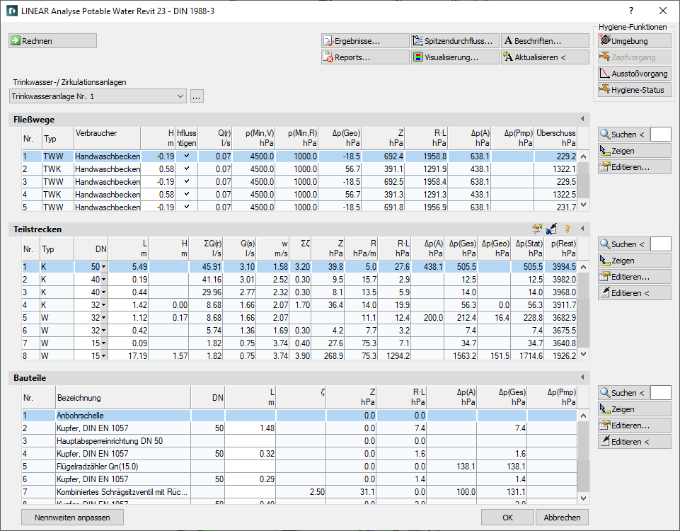
The calculation dialog shows an overview of the detected pipe network and contains all functions necessary for the calculation.
You are here:
Functions for the calculation
The functions in the upper part of the calculation dialog pertain to the entire pipe network.
| Element | Meaning |
|---|---|
 Calculate | Initiate the calculation of the pipe network after having made changes to see current calculation results. |
 Result... | Displays additional information regarding the pipe network and an overview of the calculation results, which also are part of the printouts. |
 Report... | Displays an overview of notes and errors that occurred during calculation. The color of the button helps differentiate between notes and errors: white: No notes or errors. orange: There are notes on the calculation. red: There are errors in the calculation. Note: It is recommended to always carefully read the reports to correct errors in the drawing and ensure a proper calculation. |
| Systems | If the project contains several systems or partial networks you may determine which of the systems or partial network to display in the calculation dialog’s tables. The discipline potable water differentiates between the potable water- and the circulating pipe system. |
| … | This button will open the technical data of the initial component. Here, you can change the system name shown in the drop-down list. |
 Peak flow rate... | Opens the dialog Peak flow rate, showing a detailed calculation of the peak flow rate of the selected section part with its discharge valve. You can adjust simultaneities and the building type for individual section parts in this dialog. |
 Visualization... | This function displays properties and calculation results of the pipe network in color in the model. |
 Labeling... | Label components and section parts with calculation results. |
 Refresh < | If components or section parts have already been labeled and calculation results have changed retrospectively, this button will refresh all labels with current data. |
 Ambience | Opens the dialog Simulation which allows for the simulation of the cooling or heating of potable water in a stagnant network, as well as the assignment of insulation and ambient temperatures. |
 Tapping process | The simulation of a tapping process within the model runs through after selecting a cold water consumer. |
 Ejection process | After selecting a warm water consumer, the dialog Temporal temperature profile (hot water) opens to allow for a simulation of the temporal temperature gradient of the consumer during an ejection process. |
 Hygiene status | Opens the dialog Hygiene status for visualization of rinse velocity, flow type and Reynolds number of special hygienic flushing devices or fitments directly in the model. |
| Adjust nominal diameters | If calculated nominal diameters deviate from those constructed, calculated nominal diameters can be transferred into the model. You can adjust the nominal diameters for the entire network or for partial networks. |
Functions of the tables
In sections Flow paths, Section parts and Components, similar functions are presented.
| Element | Description |
|---|---|
 Maximize list | The tables for flow paths, section parts and components can be maximized to fit the entire calculation dialog. The other tables are hidden. |
 Minimize list | This function minimizes a maximized table. The other tables are displayed again. |
 Search < | This function is available in sections Flow paths, Section parts and Components. After clicking Search < select the element in the model. The respective table then highlights the flow path, the section part or the component. If a certain flow path number, a section part number or a component number needs to be found, enter the number into the text field and click Search <. The respective table then highlights the flow path, the section part or the component. |
 Show | This function is available in sections Flow paths, Section parts and Components. First, select the element from the table and click Show. The flow path, the section part or the component is shown in the model. |
 Edit... | This function is available in sections Flow paths, Section parts and Components. First, select the element from the table and click Edit.... The dialog for editing components or section parts is opened. |
 edit in drawing < | This function is available in sections Section parts and Components. Select the element in your model after clicking edit in drawing <. The dialog for editing components or section parts is opened. |
Table for flow paths
This table shows the calculation data for all flow paths of the selected system. It provides an overview over all ending components of the network. If you select a flow path, the table Section parts displays all corresponding section parts. The most unfavorable flow path is highlighted in a different color. You can also select the most unfavorable flow path by pressing U.
| Column | Description |
|---|---|
| No. | Flow path number. |
| Type | Pipe type. PWC: Potable Water Cold PWH: Potable Water Hot PWH-C: Potable Water Hot Circulation |
| Consumer | Name of the consumer. |
| H | Height of the flow path. |
| Consider peak flow rate | Shows, whether the peak flow rate of a consumer is considered or not. The setting for the peak flow rate can be changed in the technical data of the consumer. |
| Q(r) | Calculation flow rate cold water or hot water. |
| p(Min,SP) | Minimum supply pressure at network starting point. |
| p(Min,Fl) | Minimum flow pressure. |
| dp(Geo) | Pressure loss due to geodetic height. |
| Z | Pressure loss due to zeta value. |
| L*R | Pressure loss due to pipe friction. |
| dp(A) | Pressure loss by appliances (e. g. filter, meter) and valves. |
| dp(Pmp) | Pressure recovery due to pumps. |
| Surplus | Amount of minimum flow pressure surplus for discharge valve. |
Table for section parts
This table shows the calculation data for all section parts of the selected flow path. If you select a section part, the table Components displays all corresponding components.
 Apply section part data globally
Opens the dialog Define section parts. This function allows you to assign or reset certain properties of selected or all section parts.
 Unfix / fix section parts
This function allows you to fix or unfix the dimensions of all section parts. A bold value in column DN indicates that the respective dimension of this section part will not be adjusted during calculation. This is sensible when calculating existing systems. If the dimensions of some section parts have been fixed already, you will be asked whether to fix or unfix all section parts.
| Column | Description |
|---|---|
| No. | Number of the section part. |
| Type | Pipe type PWC: Potable Water Cold PWH: Potable Water Hot PWH-C: Potable Water Hot Circulation |
| DN | Nominal diameter of pipes in this section part. The nominal diameter can be changed in the table. The value is then fixed and will not be adjusted by the software during calculation. Fixed values are shown in bold. Dimensions listed with an asterisk in the drop-down list have been disabled in the pipe tables. If special dimensions are to be used specifically, the deactivated dimensions are also available for selection here. |
| L | Length of section part. The length be changed in the table. The new length will be distributed among all pipes of the section parts proportionately to constructed length. All pipes affected by the change in length will be displayed bold in the tables for section parts and components. |
| H | Height of section part |
| U | Number of individuals ( if calculated according to SP 30.13330.2016 and SP 30.13330.2020) |
| N | Number of sanitary ( if calculated according to SP 30.13330.2016 and SP 30.13330.2020) |
| P | Probability of use ( if calculated according to SP 30.13330.2016 and SP 30.13330.2020). |
| NP | Product of the number of sanitary objects and the probability of use ( if calculated according to SP 30.13330.2016 and SP 30.13330.2020). |
| α | Simultaneity factor ( if calculated according to SP 30.13330.2016 and SP 30.13330.2020) |
| Sum Q(r) | Sum of calculation flow rates |
| Q(s) | Peak flow rate and continuous flow rate. The tooltip show, whether the peak flow rate was determined by usage unit, by curve or after a comparison of curve and usage unit. |
| v | Medium velocity. |
| Sum zeta | Sum of zeta values in this section part |
| Z | Pressure loss due to zeta value |
| R | R-value of the pipes |
| R*L | Pressure loss due to pipe friction |
| dp(A) | Pressure loss by appliances (e. g. filter, meter) and valves |
| dp(Tot) | Total pressure loss of this section part |
| dp(Geo) | Pressure loss due to geodetic height |
| dp(Stat) | Static pressure difference |
| dp(Resid.) | Residual pressure at the end of a section part |
Table for components
This table shows the calculation data for all Components of the selected section part.
| Column | Description |
|---|---|
| No. | Component number. |
| Name | Name of the component. |
| DN | Dimension. |
| L | For pipes: Length. The length be changed in the table. The new length will be used in all section parts containing the respective pipe. All pipes affected by the change in length will be displayed bold in the tables for section parts and components. |
| Zeta | Zeta value. |
| Z | Pressure loss due to zeta value. |
| R*L | Pressure loss due to pipe friction. |
| dp(A) | Pressure loss by appliances (e. g. filter, meter) and valves. |
| dp(Tot) | Total pressure loss. |
| dp(Pmp) | Pressure recovery due to pumps. |