Configuring and Inserting Tank
Shows step-by-step how to configure a tank and how to insert it into the model.
Before you begin
You want to create a tank.
Requirement:
You are in a top view or a 3D view.
Navigate to:
Applies to: Heating, Cooling, Potable water, Gas, Fire protection.
Procedure
- Select the reference level in the Construction level/ Offset (+/-) section.
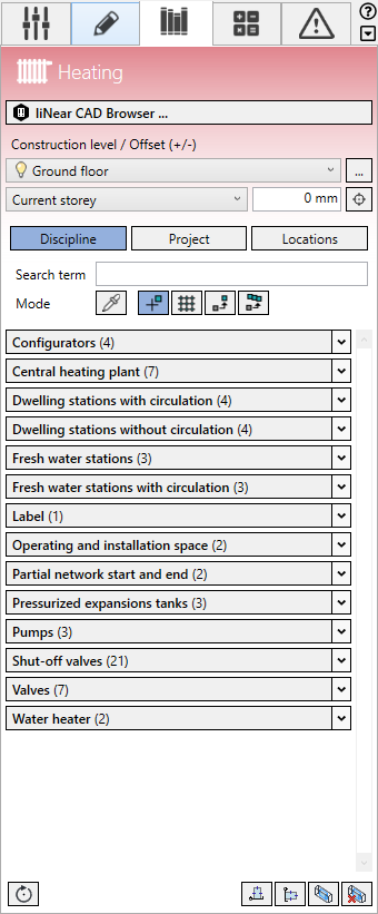
- Click Discipline.
The configurators the families of the heating discipline are displayed.
- Open the Configurators section.
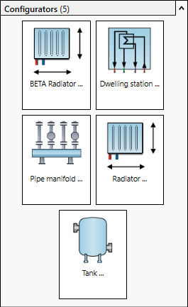
- Click Tank ....
The Tank dialog opens. The Base body tab is displayed.
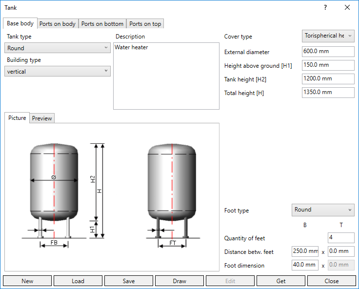
- Select the tank type and building type.
- If necessary, enter a name to name the family of the container.
- If necessary, enter a description with technical data to distinguish the tank from other configurations.
- Select the cover type.
- Enter the dimensions of the base body.
Which dimensions are to be used can be seen in the illustrations on the Picture tab. If you want to check the effects of an entry, switch to the Preview tab. Click the Refresh button after changing the settings.
- Specify the Pressure stage of the tank and adjust the wall thicknesses if necessary. Note:
No wall thicknesses are suggested for square tanks. Enter reasonable wall thicknesses manually.
- Select a foot type.
- Enter quantity, distance and dimension of the feet.
The base body is completely configured.
- If you want to attach the ports to the side of the tank, to the tank bottom or to the tank cover, switch to the related Ports on bottom, Ports on body or Ports on top tab.
The selected tab is displayed. If a port has not yet been created, the tab is initially empty.
- Click
 New port.
 The port is created and appears in the selection list. The remaining fields for defining the port are released.
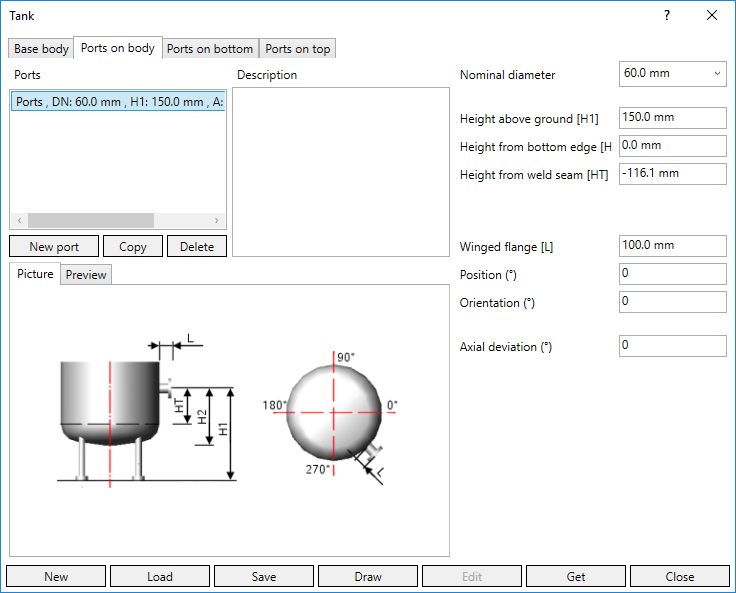
- If necessary, enter a description of the port and change the dimension and dimensions of the port.
Which dimensions are to be used can be seen in the illustrations on the Picture tab. If you want to check the effects of an entry, switch to the Preview tab. Click the Refresh button after changing the settings.
- If necessary, add more ports.
If necessary, use the function
 Duplicate port. Delete the port with the function
  Delete port.
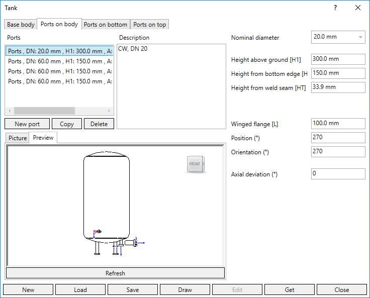
- If you also want to use this tank in other projects, click
 Save and save the configuration in a location of your choice.
 - Click Draw and place the tank in the model. Tip:
Use the space bar to rotate the component.
- Press ESC twice to exit the command.
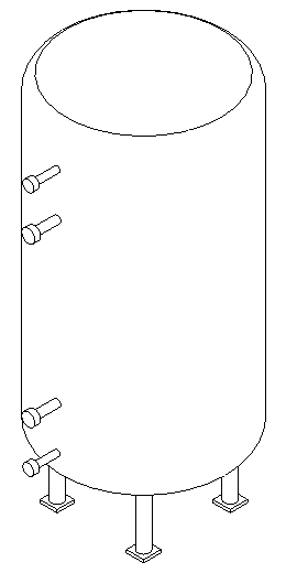
Results
The tank is inserted in the model.