Details on Ventilation Device
Information on the Ventilation device dialog in the ventilation discipline.
You are here:
Components
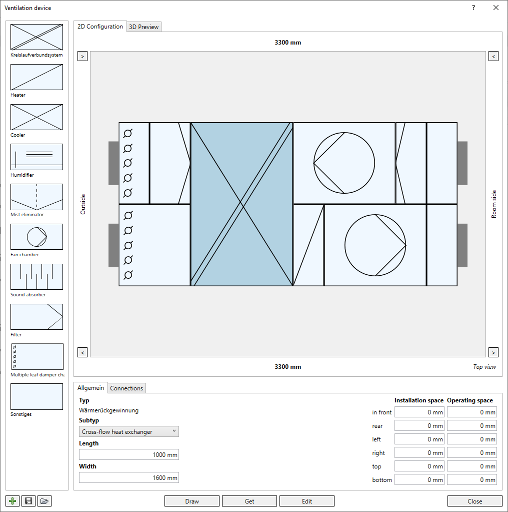
Library with components for configuring a ventilation device. Each component can be dragged and dropped to the desired position in the 2D configuration. The heat exchanger can only be installed once per ventilation unit and is hidden in the library after placing it.
2D Configuration
In this area you can drag and drop the components from the library in the desired configuration. Depending on the selected layout (horizontal/vertical), the ventilation unit can be configured in two levels (or two rows). You can subsequently move components to a different position that have already been placed using the mouse. If an already placed component is moved with the mouse while holding the Ctrl key, the respective component is duplicated and can be placed at a desired position. A selected component can be removed from the configuration by pressing Del. Alternatively, a component can be removed from the 2D configuration using drag-and-drop.
You can undo the last deletion with Ctrl+Z once.
Clicking on  at the edges of the 2D configuration changes the airflow direction of the respective plane/row. When a heat exchanger is installed, the airflow direction is set depending on the heat exchanger subtype (except for the subtype Heat exchanger general).
Basic specifications
This area is displayed if no elements of the ventilation device are selected or no components have been added yet.
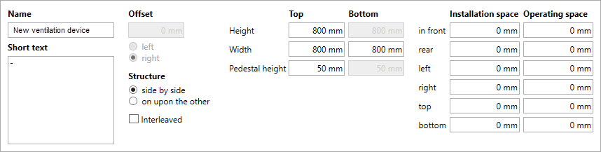
Name: The program automatically inserts a name, which can be manually overwritten with a custom name. The name must be unique in the project.
Short text: Optional description of the ventilation device.
Offset: You can configure the layers or rows with an offset to each other. Positive values shift the upper level or rear row towards the room side, negative values towards the outside. Click left or right to define the reference edge for the offset. The offset is deactivated as soon as a heat exchanger is added.
Structure: In the horizontal layout, the ventilation device is configured in two levels arranged one above the other. In 2D configuration, a side view of the ventilation device is displayed. In the vertical layout, the ventilation device is configured in two rows side by side. In 2D configuration, a top view of the ventilation device is displayed.
Nested
Enabled: The ventilation device is built from individual component families (Nested Families), which can be selected individually after installation in the model.
Deactivated: The ventilation device is built as a monolithic family, individual components cannot be selected after installation.
Height, Width, Pedestal height: You can set the height, width and level of the pedestal separately for the panels/rows of the ventilation device. The length of the air handling unit is determined by the configuration of the individual components. The length the respective plane/row is displayed above and below the view in the 2D configuration.
Installation space/Operating space: Free space for installation and operation of the entire ventilation unit. In the 3D view and after installation in the model, the entered interference spaces are displayed depending on the display setting (LoG).
General
This area is displayed when you select an inserted component.
Type: Name of the selected component.
Sub-type: If several variants of the component are available, they can be selected from the drop-down list. For the heat exchanger the sub-types Generic heat exchanger, Cross-flow heat exchanger and Rotation heat exchanger are available.
Length: The length of the component.
Width (for heat exchanger): The width of the heat exchanger. When changing the layout from horizontal to vertical, this value must be adjusted manually.
Installation space/Operating space: The possibly required installation or operating space of the selected component. In the 3D view and after installation in the model, the entered interference spaces are displayed depending on the display setting (LoG).
Connections
This area is displayed when you select an inserted component.
You can add one or more connections to the selected component. Click  to create a new connection. Click
  in the line of a connection to delete it. If a connection conflicts with the configuration of the ventilation unit, it will be highlighted in red.
| Column | Description |
|---|---|
| Form | The geometric shape of the connection. If you know the shape of the duct to be connected, you can directly make the correct setting here. |
| Position | Spatial positioning of the connection on the component. |
| Dimensions | Dimensions of the connection in height x width. |
| Length | Length of the connection. |
| x-offset/y-offset | By default, the connection is placed in the center of the selected surface. You can move the port parallel to the surface: positive values move the port to the right (x-axis) or up (y-axis). Negative values shift the port to the left (x-axis) or down (y-axis). |
3D preview
Displays the current configuration of the ventilation unit with installation and operating spaces in 3D as a wireframe model. No components can be selected for editing in this view.
Buttons at the bottom

To create a new air handling unit, the library is reset and all components are removed from the 2D configuration. Unsaved configurations are discarded.

Opens the file explorer where you can save the current configuration as an XML file in the desired directory.

Opens the file explorer where you can open previously saved ventilation devices.
Draw: Pastes the current configuration into one of the open views of your model.
Get: Hides the dialog for selecting an already placed ventilation device. The selected ventilation device is opened in the configurator and can be edited.
Edit: Transfers the changes to a fetched ventilation device to the placed ventilation device in the model.
Quit: Closes the dialog. The current configuration is saved with the project and is still available when the dialog or project is opened again.