Details on Optimization
Information about the Optimization section.
The Optimization section is a view created specifically to improve the design. It replaces or complements the Optimize button at the project, building part, storey and apartment level. In the room view you can still perform the optimization using the Optimize button in the toolbar.
Optimizations of the layout should definitely be made before the circuits are drawn.
You are here:
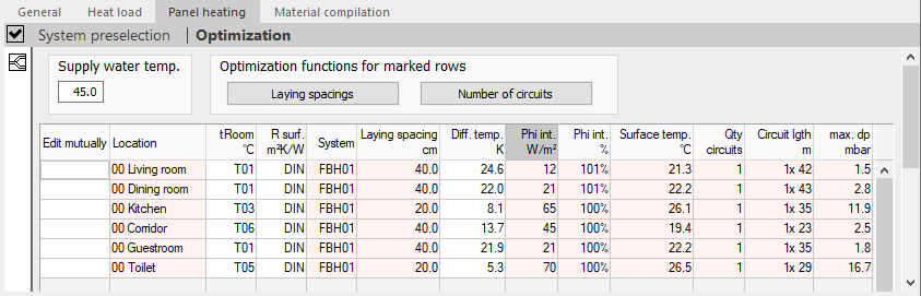
Supply water temperature
Defines the temperature of the supply water in °C.
Optimizing functions for marked lines
Displays the automatic functions to improve the design of the rooms.
Laying spacings
Optimizes the laying spacing of the marked lines in the Edit mutually column. A differential temperature optimizing is performed during a laying spacing optimization.
Number of circuits
Optimizes the number of circuits in the marked lines in the Edit mutually column. An optimizing of the number of circuits equates to a redesign, as a laying spacing and differential temperature optimization takes place at the same time.
Room table
Lists the designed rooms of the selected level and displays their parameters.
Most parameters can be adjusted directly in the table. Critical points such as over/under capacity or excessive pressure loss are highlighted in color.
If several systems with different dimensioning locations (e.g. floor and wall systems) are used in one room, the systems are listed in separate lines. Border zones and occupied zones of circuits are also listed in separate lines.
| Element | Description |
|---|---|
| Edit mutually | Determines which lines are optimized together. Clicking the column headline Edit mutually activates or deactivates all rows. |
| Location | Displays the room name and the numbers of its location in the building structure. For rooms with occupied and border zones, these are indicated by OZ and BZ. |
| tRoom °C | Determines the target room temperature. Both values as well as variables can be entered. A double click into the field or the button |
| R Surface m²K/W | Determines the thermal resistance (R-value) of the surface. A double click into the field or the button |
| System | Defines the system used. The abbreviation of the System preselection is used. A Double click into the field or the button |
| LS cm | Defines the laying distance of the pipes. A double click in the field or the button |
| Diff. temp. K | Defines the differential temperature between supply and return water. |
| Phi int. W/m² | Displays the capacity actually released. |
| Phi int. % | Displays the capacity coverage of the room in percent. The value is calculated from the capacity required for the internal room temperature and the capacity actually provided. |
| Surface temp. °C | Displays the temperature of the surface. |
| Qty circuits | Displays the quantity of circuits in the room. |
| Circuitlgth. m | Shows the total circuit pipe length, including the feed pipes. |
| max. dp mbar | Shows the circuit pressure loss with the worst pressure drop in the room. The value is formed from the pipeline pressure drop and the valve pressure drop in the open state. In circuits with flow rate controllers, the minimum working pressure is also taken into account. |
 opens the dialog
 Toolbar of the section Optimization
 Room view
Switches to the room view of the room whose zone is selected in the table.