Details on Properties (Symbols)
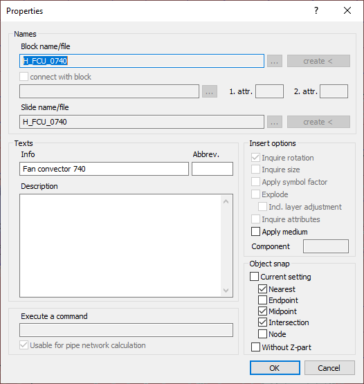
Information about the Properties dialog for component symbols.
Right-clicking the individual symbols or the placeholders for custom/free symbols opens the Properties dialog.
You are here:
Name
Block name/file
This field displays the name of the symbol block or symbol block file. If you create your own symbol, this field is editable, and you can enter a custom name.

Use this button to select a drawing file in DWG format that contains the desired component for the symbol. In the opened selection window, a file that is no longer needed can also be deleted with the Del key.
create <
This button can be used to create a symbol from an object in the current drawing, provided you have entered a file name in Block name/file. Click the button create < and select the relevant objects in the drawing.
connect with block
Select this option if you would like to insert two symbols in combination and connected with a line, as for example in the case of the differential pressure closed-loop controller symbol from the heating symbols. This will activate the fields below, where you can specify the name and path of the connected block.
Slide name/file
The slide file stores the image of the symbol that will later appear on the symbol button. It is not mandatory to enter a name for the slide file when you create a new symbol. If you do not enter a name, the block name is automatically inserted. If you select an existing file, its name will be inserted into this field.
If a slide file is available, it can be selected via this button. In the opened selection window, a file that is no longer needed can also be deleted with the Del key.
create <
If the symbol on the button is not displayed correctly, you can capture it from a drawing with create < new.
Texts
Info, Abbreviation, Description
Enter an info text and, if necessary, an abbreviation and a description of the symbol here. The text from the info field is displayed as a tooltip if you place the mouse cursor briefly on the symbol button without clicking. All three field contents are available for labeling a symbol.
Execute a command
In this field, enter a CAD command to be executed before inserting the symbol.
Usable for pipe network calculation
Here, you can set whether the button for the symbol gets the indication that the Symbol can be used in the pipe network calculation with the analysis programs. If the component is to be included in the calculation, at least one attribute is required (start or end component). Several attributes are required to connect an built-in part to a pipeline.
Insert options
Here you can activate options and commands that are known from the drawing functions of AutoCAD and that define the behavior when inserting the symbol, e.g. whether the object can be rotated before insertion or whether it should be immediately disassembled into the origin. There are several options available for inserting the symbol:
Inquire rotation
The symbol can be rotated after determining the insertion point.
Inquire size
Before determining the insertion point, the size can be entered as a factor, independent of the preset symbol factor.
Apply symbol factor
Determine whether the symbol factor should be applied or not. Three parameters are then taken into account when inserting the symbol: Scale, unity and symbol factor. Assuming it has been drawn at a scale of 1:50 in millimeters and the symbol factor is set to 0.5, the selected symbol will be inserted with an insertion factor of 25 (equivalent to 50 x 1 x 0.5) if this option is activated. If the option is deactivated, the selected symbol will be inserted with a factor of 1. The factor can be set directly in the Symbols functions section or via button to  Options on the toolbar.
Explode
If this option is activated, the symbol will be resolved into the original objects it is composed of when it is inserted. There is also an option to insert the elements on their creation layers or on the current layer. If necessary, select the option Incl. layer adjustment.
Inquire attributes
Set whether to query the attributes contained in the symbol when inserting it. After setting the insertion point and rotation of the symbol, the Attribute Editor opens, where you can enter the attribute values.
Apply medium
Symbols with this feature activated can use the Draw symbols on pipe layer toolbar options. Then the symbol is not inserted on the symbol layer, but on the same layer as the pipe.
Component
Some symbols are used in different trades, such as a water heater that belongs to both the heating and potable water trades. In order for these symbols to be controllable via QuickLayer, they are given an additional component, which is also used in the layer name. This means that water heaters remain visible in the potable water pipe network after the trade heating is deactivated via the QuickLayer.
Object snap
Select here whether the Current setting of the object snap should be used when inserting the symbol or whether you would like to determine the object snap yourself by selecting Nearest, Endpoint, Midpoint, Intersection or Node.
Without Z-part
This command allows you to draw in symbols at the current construction height and use the object snap even for objects that are located at a different height. The Z value is replaced by the current construction height. For example, if you would like to place a symbol on the 2nd floor, you can also snap to a point on the ground floor and the symbol will still be drawn at the correct height.