Details on 3D Labeling Sections
Information about the sections Label Components, 3D Pipe Label, 3D Air Duct Label, 3D Electric, Panel h./c. Label and Label Slot Planning.
With the labels listed in the sections 3D Pipe Label, 3D Air Duct Label, 3D Electric, Panel h./c. Label and Label Slot Planning, you can write design data such as dimensions, weights, distances, etc. on the components. You write the calculation data to the components using the Pipe and Duct Network Calculationlabeling function. In order to have labels available in the Label Components section, you must first configure and create the corresponding labels yourself in the Component lists dialog.
You are here:
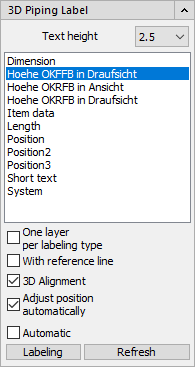
Text height
Drop-down list to select the text height to be used.
One layer per labeling type
Activated: Each labeling type is stored on its own layer when placing a label.
With reference line
Activated: A reference line is inserted between the marker and the component.
3D Alignment
Activated: The label is aligned according to the set view so that the text is always readable.
Deactivated: The labeling is aligned according to the component and the readability depends on the currently set view. Not all texts are readable in all views.
Adjust position automatically
Activated: The position of the marker automatically tracks the component.
automatic
Activated: Click all components that are to receive the selected text type (e.g. Dimension) one by one. Then press Enter to create the label automatically.
Deactivated: After clicking a component, the text (e.g. dimension) is displayed immediately. It is then placed and aligned.
Labeling
Starts the labeling command. Select a component to create the label.
Refresh
After making changes to labeled components, you can use this button to update the label.