Labeling of 3D Components with Geometric Data
Shows step-by-step how to label LINEAR 3D objects such as 3D pipes, 3D air ducts, 3D electrical cable trays, panel heating circuits and FH manifolds with geometric data.
Before you begin
You would like to label the 3D objects of your pipe or duct network with geometric data.
Requirements:
You have a drawing with 3D objects.
Navigate to:
Note:
3D labels are available only in 3D construction of air ducts, pipes and electric cable trays, as well as in 3D floor planning of panel heating/cooling. Architectural elements cannot be provided with the 3D labels.
Procedure
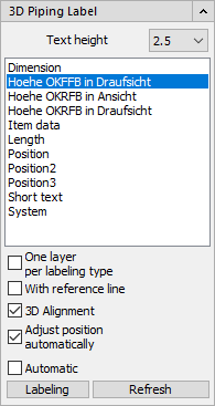
- Optional: Change the text height for the labeling text.
- Select a label for the components to be labeled from the list, e.g. Item data. Note:
Different predefined labels are available in the different trades.
- Make further settings for the labeling. Define, for example, whether a reference line should be generated between the label and the component.
- Click Labeling.
- Select the component to be labeled in the drawing. Note: If you have selected the Automatic option, you have to select all components to be labeled in the drawing first and confirm this selection with Enter.The label is created and is attached to the mouse pointer.
- Select the position of the label with the first click.
- Use the position of the cursor to adjust the orientation of the label.
- Click the mouse to confirm the position and orientation of the label.
Results
The label is now placed.