Details on Dimensioning/Label
Information about Dimensioning/Label.
Dimensioning/Label contains different commands depending on the selected assistants. Which assistants are present on your computer depends on the program version and licensing. Therefore, not all command documented here may be available to you.
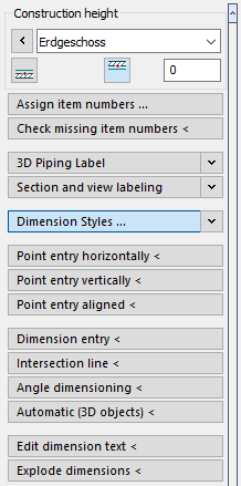
Construction height
In the Construction height section, you determine the height at which objects are drawn by setting the storey, reference edge and, if necessary, an offset.
Assign Item Numbers ...
Opens the Assign item numbers dialog where you can adjust the setting for assigning item numbers and start the assignment.
Check missing item numbers <
This command allows you to check if item numbers are assigned to all components in the drawing.
3D Labeling: 3D Piping labels, 3D Air duct labels, Panel h./c. labels, Label components, Label slot planning.3D Electrical
In the sections 3D Piping labels, 3D Air duct labels, Panel h./c. Labels,, Label components, Label slot planning or 3D Electrical you can adjust the settings for the used label blocks of 3D objects.
Section and view labeling
Allows you to adjust the settings of the section and view labelling and the execution of the command.
Text settings
Enter the text settings in this section.
Writing <
Starts custom text input, which allows you to place text anywhere in the drawing. There is no automatic line break, nor can it be performed subsequently. However, you can press Enter to start a new line. Each new line is a separate text object. You can change the text style later by selecting the text and choosing a different text style or style feature.
Edit <
This command allows you to select text objects or room labels for editing.
Dimension styles ...
The dimension style defines certain properties of the dimension text and the display of the dimension line. If necessary, define a different dimensioning style here or open the Dimension: dialog by clicking Dimensioning styles ... (...) which allows you to customize the dimension styles and create new ones. The included dimension styles are available in text sizes 18 to 70. Styles for architecture dimension in the unit meter, those for building services in mm.
Point entry horizontal <, Point entry vertical <, Point entry aligned <
Allows you to draw in dimension chains. The procedure of dimensioning by point entry is always the same for the three variants horizontal, vertical and aligned and only differs in the alignment of the dimensions and the dimension chain. Pick up two points in your drawing and determine the location of the dimension chain. The dimension (measured horizontally, vertically or along a previously defined line) is then automatically written to the dimension chain. After that you have the possibility to add more points to the same dimensional chain. Set the unit of measurement and font sizes beforehand under Dimension styles.
Dimension entry <
With this dimensioning you determine the first point of the dimensional chain. The length of the dimension chain is defined via the dimension entry. Set the unit of measurement and font sizes beforehand under Dimension styles.
Intersection line <
This command creates a horizontal dimension chain based on intersection points of the intersection line with the objects to be dimensioned. For example, you can dimension a house wall. For the dimension chain, a section line is drawn through the objects to be dimensioned. The intersection line can have several support points, so that you can omit or specifically include certain objects.
Angle dimensioning <
Use this command to label angles in your drawing. After starting the command, you can click on a point on each leg of the angle to enter the angle measure yourself or accept the proposed value.
Automatic (3D objects) <
This automatic length labeling was developed for 3D pipes in layout. The settings from the Dimension Styles area are used for this purpose. You can choose between the length dimension and the axis dimension of the tube. The labels are placed directly next to the pipeline, depending on the view currently set.
Edit dimension text <
This command allows you to change the length dimension and add an opening dimension.
Explode dimensions <
The dimension elements are grouped. You can recognize the group by the fact that dimension lines and font are both marked when you click on them. You can use this command to ungroup them.
After resolving the dimensioning, all dimensioning elements can be selected individually. All dimensions of the entire drawing are resolved. If you want to resolve individual dimensions, use the AutoCAD Explode command from the Modify group on the Home tab of the AutoCAD Ribbon.