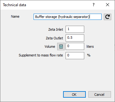
In this dialog, you define the technical data for buffer storages (hydraulic separators).
You are here:
The Buffer Storage Component (Hydraulic Separator) behaves like a hydraulic separator. It is used between the flow and return pipes and ensures hydraulic separation of the pipe network and thus also separation of the flow paths. A pump must be installed in both the primary and secondary circuits to ensure the supply pressure is maintained.
Name
In this field you can enter an individual name for the component. Clicking on  restores the original name and overwrites the previous entry.
Zeta Inlet, Zeta Outlet
You can use these two input fields to adjust the resistance coefficients for the inlets and outlets of the component in order to map the pressure loss of the entire component. The default values are 1 for the inlet and 0.5 for the outlet.
Volume
Defines the capacity of the component in liters. The volume entered is then transferred to the Designation of the component. Click  to reset the volume to the value from the calculation. The value is used to calculate the system volume and to design the diaphragm expansion tank, if a diaphragm expansion tank is used in the model. If the volume is not entered, a warning appears during the calculation.
Surcharge to Mass Flow Rate
Enables the definition of a percentage mass flow surcharge. This increases the mass flow on the primary side in order to ensure a sufficient supply for the secondary side. Mass flow surcharges can lead to a temperature increase in the connected flow and return lines of the primary circuit.