Details on the Calculation Dialog for Open Drainage
Information about the Open Drainage Calculation dialog.
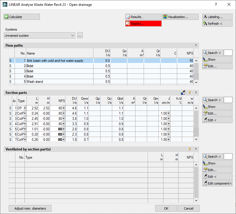
The calculation dialog shows an overview of the detected pipe network and contains all functions necessary for the calculation.
You are here:
Functions for the calculation
The functions in the upper part of the calculation dialog pertain to the entire pipe network.
| Element | Meaning |
|---|---|
 Calculate | Initiate the calculation of the pipe network after having made changes to see current calculation results. |
 Result... | Displays additional information regarding the pipe network and an overview of the calculation results, which also are part of the printouts. |
 Report... | Displays an overview of notes and errors that occurred during calculation. The color of the button helps differentiate between notes and errors: white: No notes or errors. orange: There are notes on the calculation. red: There are errors in the calculation. Note: Please always read the report very carefully to correct the errors contained in the model and to ensure a correct calculation of your pipe network. |
| Systems | If the project contains several systems or partial networks you may determine which of the systems or partial network to display in the calculation dialog’s tables. |
| … | This button will open the technical data of the initial component. Here, you can change the system name shown in the drop-down list. |
 Visualization... | This function displays properties and calculation results of the pipe network in color in the model. |
 Labeling... | Label components and section parts with calculation results. |
 Refresh < | If components or section parts have already been labeled and calculation results have changed retrospectively, this button will refresh all labels with current data. |
| Adjust nominal diameters | If calculated nominal diameters deviate from those constructed, calculated nominal diameters can be transferred into the model. You can adjust the nominal diameters for the entire network or for partial networks. |
Functions of the tables
In sections Flow paths, Section parts and Ventilated by section part(s) similar functions are presented.
| Element | Description |
|---|---|
 Maximize list | The tables of flow paths, section parts and ventilation section parts can be enlarged over the entire calculation dialog. The other tables are hidden. |
 Minimize list | This function minimizes a maximized table. The other tables are displayed again. |
 Search < | This function is available in sections Flow paths, Section parts and Ventilated by. Select the element in your model after clicking Search <. The respective table then shows the flow path, the section part or the ventilation section part. If a certain flow path number, a section part number or a ventilation section part number needs to be found, enter the number into the text field and click Search <. The respective table then shows the flow path, the section part or the ventilation section part. |
 Show | This function is available in sections Flow paths, Section parts and Ventilated by. First, select the element from the table and click Show. The flow path, the section part or the ventilation section part is shown in the model. |
 Edit... | This function is available in sections Flow paths, Section parts and Ventilated by. First, select the element from the table and click Edit... The dialog for editing drainage element, section part or ventilation section part is opened. |
 edit in drawing < | This function is available in sections Section part, and Ventilated by. Select the element in your model after clicking edit via drawing <. The dialog for editing section parts is opened. |
| Edit component data via drawing < | This function is available in section Ventilated by. Select the component in your model after clicking edit via drawing <. The dialog for editing the component is opened. |
Table for flow paths
This table shows the calculation data for all flow paths of the selected system. It provides an overview over all ending components of the network. If you select a flow path, the table Section parts displays all corresponding section parts. The most unfavorable flow path is highlighted in a different color. You can also select the most unfavorable flow path by pressing U.
| Column | Description |
|---|---|
| (without title) | Pipe type: C: Sewage water R: Rain water |
| No. | Flow path number. |
| Name | Name of the drainage element. |
| DU | Connection value |
| Qc | Water inflow. |
| A | Connected roof area. |
| Qr | Rainwater outflow rate. |
| C | Discharge coefficient. |
| NPS | Dimensioning target. |
Table for section parts
This table shows the calculation data for all section parts of the selected flow path. If you select a section part, the table Ventilated via section part(s) displays all corresponding ventilation section parts.
 Apply section part data globally
Opens the dialog Define section parts. This function allows you to assign or reset certain properties of selected or all section parts.
 Unfix / fix section parts
This function allows you to fix or unfix the dimensions of all section parts. If values are displayed in bold in the DN column, the dimension of the respective section parts will not be adjusted during the calculation. This is sensible when calculating existing systems. If the dimensions of some section parts have been fixed already, you will be asked whether to fix or unfix all section parts.
| Column | Description |
|---|---|
| (without title) | Pipe type: C: Sewage water R: Rain water M: Mixed water |
| No. | Number of the section part. |
| Type | DP: Down pipes G: Ground pipe ColP: Collector pipe C: Collecting pipe SCP: Single connector pipe (int): inside the building (ext): outside the building Pipe type can be changed in the table. |
| L | Length of section part. The length be changed in the table. The new length will be distributed among all pipes of the section parts proportionately to constructed length. All pipes affected by the change in length will be displayed bold in the tables for section parts and components. |
| H | Height of section part. |
U | Number of individuals ( if calculated according to SP 30.13330.2016 and SP 30.13330.2020) |
| N | Number of sanitary ( if calculated according to SP 30.13330.2016 and SP 30.13330.2020) |
| P | Probability of use ( if calculated according to SP 30.13330.2016 and SP 30.13330.2020). |
| NP | Product of the number of sanitary objects and the probability of use ( if calculated according to SP 30.13330.2016 and SP 30.13330.2020). |
| α | Simultaneity factor ( if calculated according to SP 30.13330.2016 and SP 30.13330.2020) |
| NPS | Nominal diameter of pipes in this section part. The nominal diameter can be changed in the table. The value is then fixed and will not be adjusted by the software during calculation. Fixed values are shown in bold. |
| DU | Connection value. |
| Qww | Waste water discharge. |
| Qp | Pump flow rate, if a pump exists. |
| Qc | Continuous flow rate. |
| Qtot | Total waste water discharge. |
| A | Connected roof area. |
| Qr | Rainwater outflow rate. |
| Qm | Mixed water outflow. |
| J | Slope. The slope can be changed in the table. |
| h/d | Filling degree. The tooltip in this field shows the actual- and max-condition of the current loads. |
| w | Flow velocity in collecting- and ground pipes. |
Table Ventilated by section part(s)
This table shows the calculation data for all ventilation section parts of the selected section part.
Unfix / fix section parts
This function allows you to fix or unfix the dimensions of all section parts. The column NPS displays all values in bold and section part dimensions are not adjusted during calculation. This is sensible when calculating existing systems. A repeated click on this button unfixes all dimensions. If the dimensions of some section parts have been fixed already, you will be asked whether to fix or unfix all section parts.
| Column | Description |
|---|---|
| (without title) | Pipe type: L: Ventilating pipe |
| No. | Number of the ventilating pipe. |
| Type | Type of ventilation pipe. The ventilation pipe can be changed in the table. |
| L | Length of section part. The length be changed in the table. The new length will be distributed among all pipes of the section parts proportionately to constructed length. All pipes affected by the change in length will be displayed bold in the tables for section parts and components. |
| H | Height of section part. |
| NPS | Nominal diameter of pipes in this section part. The nominal diameter can be changed in the table. The value is then fixed and will not be adjusted by the software during calculation. Fixed values are shown in bold. |