Details on the Heating Load Calculation in the Room
Information on the Heat load calculation according to SP 60.13330.2016 section at room level.
You are here:
General room data
The room number, room name, room temperature and room geometry from the general room data are displayed in the area above the table. Click  to open the Room data dialog, where you can adjust information on room geometry.
Standard ventilation heat load: Opens the Standard ventilation heat load dialog, where you can configure information on minimum air circulation for hygiene, infiltration, air change, and mechanical ventilation.
Simplified view: Reduces the number of table columns displayed.
Room humidity: Drop-down list to select the room humidity for this cell. The combination of regional humidity and room humidity is used to determine if the dry or wet thermal conductivity of a building material is used to determine U-values.
Heat gain: Rooms with a room temperature between 18 °C and 26 °C are defined as living rooms according to the standard. The value entered here is applied to living rooms from the general heat load data of the project level. This value can be adjusted for each room.
β1 and β2:
β1 and β2 are additional heat losses that can be considered as correction factors in the dimensioning heat load of the room according to AVOK 2.3-2012. Both factors are multiplied by the standard heat load. Correction factors at the project level apply to all rooms in the project. Correction factors entered manually at room level are not overwritten and have priority in relation to the values at project level.
β1: The value depends on the location and nature of the heating device in the room. Click  to open a table with values from AVOK 2.3-2012.
β2: A free entry at your own discretion is possible here and therefore no table is provided. Click resets the input value to 1.
Add. heat consumption: Additional coefficient that takes into account heat consumption for heating material, equipment and vehicles.
Table with component data
Abbrev. of ID - Abbreviation number Abbreviation for the type of component. The software differentiates between predefined components from the master tables and component types. The predefined components are defined in more detail via the numbering and can already contain U-values and dimensions. Predefined components can be adjusted in the master tables.
You can enter an abbreviation for the type of component or a component directly in the column. Alternatively, you can select a component or a component group from the table by pressing F8 or by clicking  . The following component types are available for selection:
| Component code | Component |
|---|---|
| EWA | Exterior walls (also adjoining to ground) |
| EWI | Exterior windows |
| ED | Exterior doors |
| RF | Roof |
| RW | Roof window |
| CL | Ceiling |
| FL | Floor |
| IWA | Interior walls |
| IWI | Interior windows |
| ID | Interior doors |
| Z | Additional other heating load in the room (not to be confused with the additional heating-up capacity). |
| DAR | Pure deduction area this area is considered to be an opening without any thermal calculation. |
Adjoins: Indicates whether the component adjoins a heated or unheated room, or the ground or outside air. If this building was acquired from a CAD, these values are automatically entered. Clicking  opens the Component adjoins dialog, where you can chose from the following input options, depending on the component:
| Code | Explanation | Available for component |
|---|---|---|
| e | External (adjoining the outside air) | EWA, EWI, ED, RF, RW, FL |
| g | Ground (adjoining the ground) | EWA, FL |
| u | Surface adjoins an unheated room | IWA, IWI, ID, CL, FL |
| i,j | Area adjoins a heated room or the same room |
The codes can also be entered directly via the keyboard.
OR - Orientation: Cardinal point in which the component or area is located. It is used to identify the gross area and, in the case of the GEG/EnEV, also to determine the solar heat gains of exterior windows, transparent insulation and glazing (winter gardens). Deduction areas are not given a cardinal point. Instead, these areas are marked with -- as deduction area (a "-" is sufficient as input). The specification H (horizontal) can be used for ceilings, floors, roofs and roof windows.
N - Number of equal areas: The number of equal areas is a multiplier. The input is limited to whole positive numbers without decimal places. If areas are to be considered only partially, the values of the Width and Height columns can be adjusted accordingly.
W - Width, h/l - Height and Length, A - Area, A’ - Net area:
In these four columns you define the width, height, length or area of the heat-transferring outer area. If the width, height or length is entered, the area is calculated from the data. If the area is entered, the entries for width, height or length are deleted. In column A’ the area minus all deduction areas is displayed.
In these fields it is possible to enter dimensions as a term. Enter the term e.g. with 2.25+1.35 and press Enter. The result is calculated and entered. For areas that are to be only partially included in the calculation, such as gable walls, the dimensions can be entered with an appropriate factor (e.g. 0.5*width*height for triangular areas).
Z(i): Zoning required by standards for all walls and floors adjoining the ground. At distances of two meters the components adjoining the ground are assigned to zones I to IV. Zone I adjoins the ground surface, and Zone IV is the most interior test surface, which has a distance of more than six meters to the ground surface along the components in contact with the ground.
U-value: Enter a U-value directly as a number, or use F8 or click an already calculated U-value from the list. To be able to take room humidity into account, select the U-values for walls, ceilings, floors and roofs from the master tables as composite layers, and ensure that a distinction is made between moist and dry for the lambda values. For windows and doors a numerical value of the U-value is sufficient.
If the U-value is entered as number for surfaces adjoining the ground and not stored in the master tables as layered component, zoning is not taken into account. An error is issued which can be switched off in the configuration.
Variable U-value of components with layer composition
If a variable U-value of a component with layered structure is used, the heat load takes into account the heat transfer resistances specified in the general heating load data. This makes it possible to use the same component (e.g. B01) once as an exterior wall (e.g. the south wall in the living room) and once as an interior wall. The correct transfer resistances are automatically taken into account.
The same applies to ceilings and floors, where the heat transfer resistances are correctly assigned according to the heat flow density. The same floor towards a colder room (heat flow direction downwards) has different heat transfer resistances compared to a room with higher temperatures.
The differentiation of a component according to the heat flow direction or the type of use (EW or IW) is therefore no longer necessary when defining the component in the U-value calculation.
ΔU(tb) – thermal bridge addition: The thermal bridge addition is to be added to the physical U-value of the exterior surface. For building components facing heated rooms, the thermal bridge addition is disregarded. In the master tables you can create variables for the thermal bridge additions.
U(o) – total U-value: The total U-value of the component results from the physical U-value and the thermal bridge addition. Moreover, with components adjoining the ground the R-value is included in the calculation of the U-value.
R-Ins: For floors, walls and ceilings an additional thermal resistance can be taken into account for the wall or floor covering, which is based on the material and the material thickness. Enter the value directly or click to open a table where you can select the desired value.
ta °C: Adjoining temperature for the reverse side of the respective component. For exterior components the outside temperature of the location is automatically adopted.
Cf.-n – coefficient n: The transmission heat loss of the component can be reduced through the coefficient, depending on the composition of the component and on what the component adjoins to. Click to open the Coefficient n dialog, where you can select from predefined coefficients.
Additional beta: Additional adjustment of transmission heat loss, dependent on the geometric properties or general building types. Click to open the Additional beta value dialog, where you can select from a list of predefined values.
QT: The transmission heat loss of the respective component.
G – air permeability value: Indicates air permeability of walls, doors and windows. This value can be entered directly; it is used in the detailed determination of infiltration heat losses of exterior components. Click to open the Air permeability G in kg/(m2h) dialog, where you can select from a list of predefined values.
R(inf) – air resistance: For exterior windows and doors, air resistance is queried. It helps provide a detailed determination of the infiltration heat losses of exterior components. The value is first calculated, and depends on building height, the G-value, the inside-outside temperature difference, as well as the inside-outside pressure difference.
If you know an R(inf) from the manufacturer and enter the value manually, the G-value is grayed out and not used any more. With the delete button the manually entered values can be reset to the calculated values.
Joint surface – Proportion of joint surface: The dimensionless proportion of the joints of a surface (of a brick wall, for example) can be entered manually, to reduce the surface for infiltration to be specified. It helps provide a detailed determination of the infiltration heat losses of exterior components. If there are no joints, leave the value at zero.
k – heat flow factor; influences the infiltration of permeable components. Click to open the Heat flow factor k (infiltration) dialog, where you can select from a list of predefined factors.
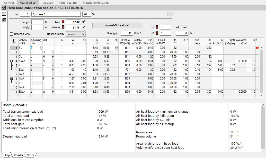
Results tab
Room heat load is broken down into transmission heat loss, ventilation heat loss and heat gain in the section on the left. Total heat load, the area and volume-specific room heat load, and additional loads based on the correction factors beta 1 and beta 2 continue to be listed.
The section on the right of the tab contains the results of the calculation of standard ventilation heat load. The respective largest ventilation heat loss is fed into the calculation of room heat load under Total ventilation heat load.