Details on System Component Panel Heating/Cooling
Information about the System component panel heating/cooling tab.
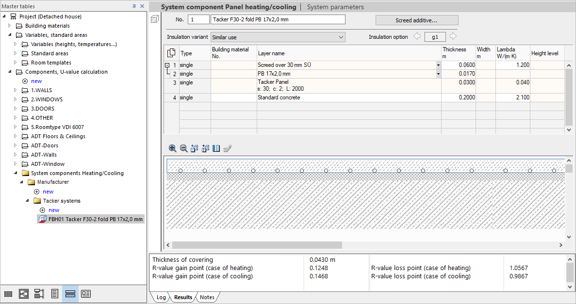
Tabular and graphical display of the layers of the system component selected in the master tables. Components can be modified, depending on the system. Modifications are only possible within predefined limits and in released fields. Adding additional layers is always possible.
You are here:
System component Panel heating/cooling
The number and name of the component are displayed. Both can be adjusted here.
Depending on the system, you can use the Screed additive... button to open the Select the screed additive dialog, in which screed additives from the manufacturer can be added to the parts list.
Under Insulation variant, different insulation variants can be assigned to the system component. Decisive is the type of use of the adjacent room to the panel system or the nature of the adjacent material. According to the specification, the corresponding R-value is adopted according to the standard and used for the calculation. The following insulation variant are possible.
-
similar use
-
non-similar use
-
unheated room
-
Outside air
-
Ground
Depending on the system, it is also possible to choose between different insulation options.
Tabular display of the system component
Lists the individual layers and their parameters.
Depending on the system, some layers and their parameters can be modified. With F5 or a click in an empty line new layers can be added. Modifiable layers can be removed with F6. Depending on the system, variants are offered in some layers, between which you can toggle with the  button.
Layers marked in the table are highlighted in the graphical layer editor.
| Column | Description |
|---|---|
| Number | Numbering of the individual layers of the system component, starting with the top layer. Layers or elements of the component located within another layer (pipes in the screed) are marked with |
| Type | Defines whether a layer is simple (continuous layer) or composite (repeating element, such as beams in a timber beam ceiling). This is fixed for the layers of the system components of the panel heating/cooling. |
| Building material No. | Displays the Material No. for added layers that have been modified regarding the building material. Tip: The number allows you to insert a building material directly into the component listing or the U-value calculation. In unlocked fields opens Note: Since these are systems supplied by the manufacturer with a fixed structure, not all layers can be replaced or edited. |
| Layer name | Displays the name of the corresponding layer or its building material. Depending on the layer, you can choose between different variants via the button |
| Thickness mm | Indicates the vertical extent of the layer. |
| Width m | Indicates the horizontal extent of the layer. |
| lambda W/(mK) | Specifies the thermal conduction coefficient of the layer required for the calculation of the U-value. |
| Height level | Allows you to take into account the height of the pipe in the pipe-routing layer. In some systems, such as stapled systems, the pipe is always on the base of the layer. In these systems, the default height is 0.0 and is not shown. With systems such as industrial and concrete core conditioning systems, you can take the location of the pipe in the layer into account by stating the height. |
 .
.  the
the Graphical layer editor
Enables processing of the system component. Selecting a layer selects the corresponding line in the layer table.
 : Enlarges or reduces the display of the current layer structure.
 : Opens the Material List dialog for selecting a building material and allows you to insert the selected building material at the selected position.
 : Allows you to insert a free layer with self-defined building material at a selected position.
 : Opens the Select type of air layer dialog where you can define a dead or weakly circulating air layer. You can then insert the layer with a click at the desired position in the layer view.
 : Removes the currently selected layer. As these are systems supplied by the manufacturer with a fixed structure, not all layers can be deleted.
Pipes can generally not be removed from the layered structure.
Header area system component panel heating/cooling
 : Switches to the Table of building materials. As soon as a building material of a layer has been replaced or a new layer with a building material has been added, the button can be activated. Activation is done by selecting the edited or added layer in the table. The Table of building materials lists all entries of the building material category of the building material assigned to the layer.