Details on Drainage in the Settings Waste Water
Information about the Drainage tab in the Settings dialog in the pipe network calculation waste water.
In this tab you can determine global settings for the calculation. Select the calculation method and the building type, specify minimum slope and determine global settings for technical data of toilets. The settings are saved with the project.
You are here:
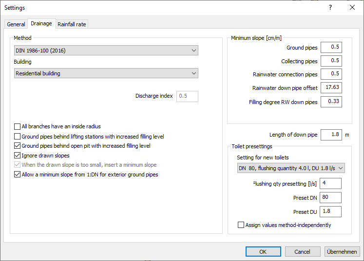
Method
| Element | Meaning |
|---|---|
| Calculation basis | Select the calculation basis. |
| Building | Select the building type. Selecting the building type also automatically specifies the discharge index. When selecting Special building, the discharge index can be changed. |
| Discharge index | The discharge index depends on the selected building type. When selecting Special building, the discharge index can be changed. If for some sections of the pipe network discharge indexes are to deviate, they can be changed using the function Edit section part data in the calculation dialog. |
| Apply recommendations of SN 592 000:2012 | This option is available in the waste water method SIA SN 592 000:2012. If you select the above method, the option will be activated automatically. Enabled: The national recommendations of the Swiss standard for the dimensioning of the pipe system are taken into account in the calculation. Disabled: Instead of the recommendations of the Swiss standard, the boundary conditions of EN 12056 are taken into account in the dimensioning of the pipe system. |
| All branches have an inside radius | Enabled: Calculation is based on the assumption that all branches have an inside radius. This can affect the dimensioning of down pipes. This property can also be set in the technical data of individual branches using the function Technical data in section Components. |
| Ground pipes behind lifting stations with increased filling level | Enabled: Ground- and collecting pipes behind lifting stations are dimensioned using a higher flow rate. This makes for smaller dimensions. It can be combined with the option Ground pipes behind open pit with increased filling level. Sewage water: Filling degree for ground pipes inside the building, behind lifting stations. 0.7 Sewage water: Filling degree for ground pipes outside the building behind lifting stations and open pits: 1 |
| Ground pipes behind open pit with increased filling level | Enabled: Ground- and collecting pipes behind open pits are dimensioned using a higher flow rate. This makes for smaller dimensions. It can be combined with the option Ground pipes behind lifting stations with increased filling level. Mixed water: Filling degree for ground pipes starting at DN 150 inside the building behind, behind open pits: 1 Rainwater: Filling degree for inside or outside ground pipes behind open pits: 1 |
| Ignore drawn slopes. | Enabled: Waste water pipes are calculated using the minimum slope. Disabled: Waste water pipes are calculated using the drawn slope. |
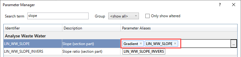
| When drawn slope is too small, insert a minimum slope | Enabled: If the slope of drawn waste water pipes turns out to be smaller than the minimum slope, the minimum slope is used for calculation. Note: To ensure that the slope constructed in Revit is correctly considered, it is necessary that the Revit parameter Slope is assigned to the LINEAR parameter LIN_WW_SLOPE in the first position in the Parameter Manager, so that the parameter Slope is read out first.
|
| Allow a minimum slope from 1:DN for exterior ground pipes | Enabled: The minimum slope of exterior ground pipes is made independent from their dimension. Note: For large dimensions, the minimum slope of ground pipes may be undercut. |
Minimum slope
A minimum slope can be specified for different pipe types.
| Pipe type | Standard value for minimum slope |
|---|---|
| Ground pipe | 0.5 cm/m |
| Collecting pipes | 0.5 cm/m |
| RW connection pipes | 0.5 cm/m |
| Rainwater down pipe offset | 17.6327 cm/m (=10°) A down pipe with less than 10° slope will be dimensioned according to rules for collecting pipes. A down pipe with equal or more than 10° slope will be dimensioned according to rules for down pipes. |
| Filling degree RW Down pipes | 0.33 |
| Slope limits | This option is available if the SIA SN 592 000:2012 waste water procedure is selected and is activated accordingly. The fields for manual entry of the minimum slopes are then deactivated. Use the button to open the Minimum slope according to SIA SN 592 000:2012 dialog, which lists the specifications for the slope limits from the underlying standard. |
Length of down pipe
Defines the length from which pipes are recognized as down pipes.
Depending on the project, it may be useful to reduce the length of down pipe so that down pipes with a length of less than 1.8 m are also recognized as down pipes and not as collecting pipes pipes. This guarantees that associated ventilating pipes are correctly detected and adjusted.
If a down pipe is detected as a collecting duct and a secondary ventilation is connected above the down pipe, it is possible that the dimension of the secondary ventilation is applied to the actual main ventilation, since without a down pipe the main ventilation is not detected correctly.
Toilet presettings
All toilets added to the model as new components will receive the here selected presettings.
If already placed toilets are to receive new settings, the pipe network needs to be recalculated beforehand. Change the toilet presettings following the recalculation. You can decide whether or not to update all toilets in the model in the subsequent dialog.
| Element | Description |
|---|---|
| Sample selection | For each calculation basis, different samples for flushing quantity, dimension DN and connection value DU are available. |
| Flushing quantity presetting Preset DN Preset DU | The value from the selected sample is shown. You can change the value manually. Note: The preset value is read from an external file. If you manually enter a value that does not exist in that external file, the first entry from the external file will be used. This value deviates from the manually entered one. |
| Assign values method-independently | Enabled: Input values are used as basis for flushing quantity, dimension and connector value. The external files from which these values are taken will not be checked. |