
BIM is often presented as a multi-dimensional design methodology, in which a 3D model is enriched with information on scheduling (4D), cost control (5D), sustainability (6D), and so on. Each new dimension after the time axis does not stand for a physical dimension, but rather metaphorically for additional degrees of freedom that can be added to the model. This is remarkable, since the term dimension is used only partially in its actual sense. This can create the impression that the higher dimensions are downstream in the design process and can be viewed as "optional". However, costs are an essential indicator of whether a project will be pursued at all. Misguided optimization can happen to the detriment of operating costs, which has a negative impact on life cycle costs and possibly on the sustainability of the building. The higher "dimensions" such as cost and sustainability must therefore be considered early in the design process.
In practice, such considerations are - if at all – unfortunately often only considered at a late stage. The actually enormous work step in the early service phases 1 to 3, in which a three-dimensional building model is to be created from a requirements planning, does not require a separate mention in most popular displays of the BIM method. This is presumably due to the fact that the involved architects usually create initial three-dimensional models on the basis of intuitive considerations. The depth of depiction of technical facilities is often kept to a minimum, since technical access areas, in contrast to utility and traffic areas, have no representative value.
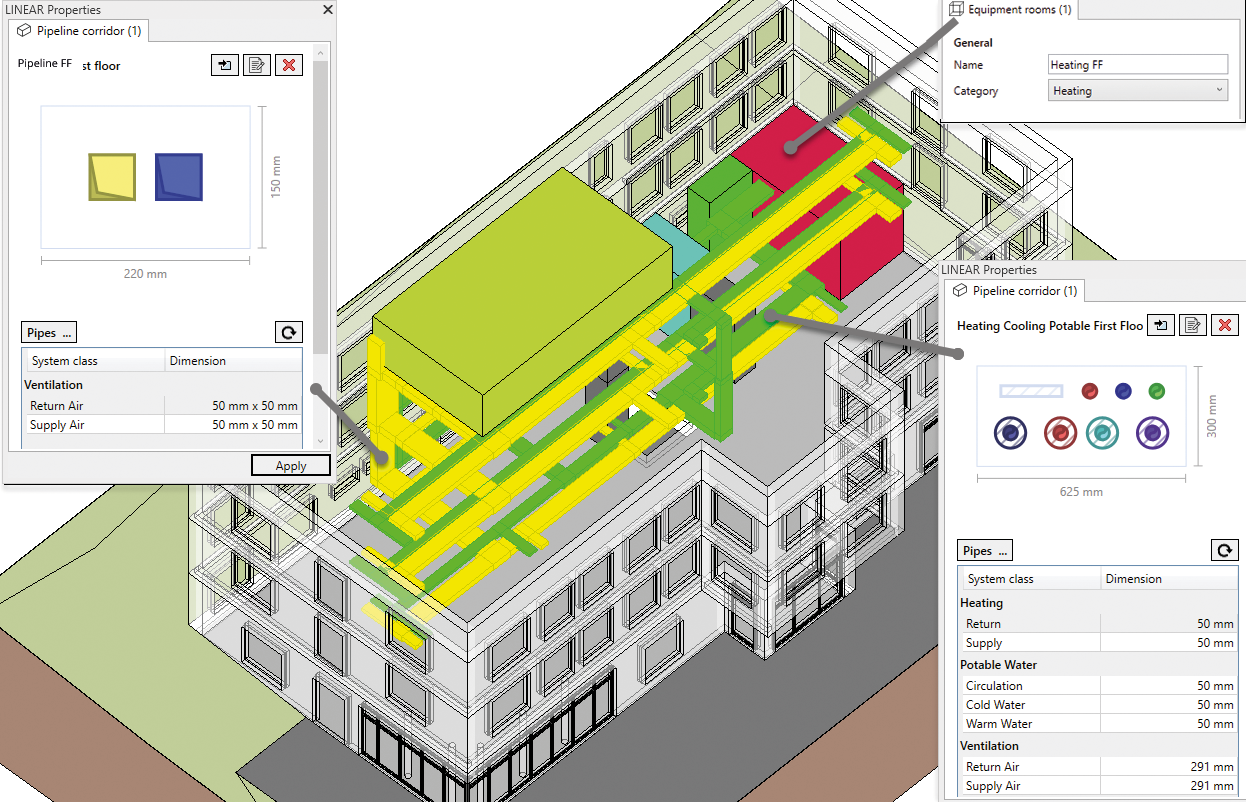
In order to break through the conflict of objectives between architectural, construction, and system engineering area and space requirements, DIN EN ISO 19650 proposes a so-called federation and information container division. What does this mean? Well, the aim is to essentially allow different task teams to work on parts of the information model simultaneously without introducing spatial or functional incompatibilities. The approach of the so-called "BIM according to ISO 19650" essentially aims to increase information security and to create a structural framework for collaboration - and this, if possible, before the individual teams delve into detailed design tasks. To this end, spatial boundaries are to be defined within which each task team should find the systems, components, or building elements for which it is responsible. ISO 19650 distinguishes between primary linear and spatially complex structures. Primary linear structures, such as shafts or pipeline corridors, can be represented by a dimensioned cross-section; more complex situations are ideally represented by a collection of interlocking obstructions. A pleasant side effect: In working practice, a permanent superimposition of different detail models is thus obsolete; for many coordination tasks, the exchange of lightweight information models is sufficient.
The design approach taken by the LINEAR software in early phases appropriately represents these recommendations in the discipline "pipeline corridor concept". It extends the basic ideas with intelligent information containers for the structural mapping of necessary spaces for different technical media and electrical systems. This simplifies the design and documentation of pipeline corridor cross-sections by using intuitive tools. The given information is also used to support the dimensioning of the necessary information containers and to simplify the transition to detailed design phases. This makes it possible to agree on space requirements at an early stage using lightweight models.
One of the main challenges in creating three-dimensional design models is that classical modeling techniques do not permit a flexible response to changes. If you work at a modeling level where the involved trades have already built at the component level, even the simplest changes will require time-consuming modifications. In the following, we would therefore like to outline an alternative approach that makes it possible to work together in early design phases towards a three-dimensional pre-concept design model that forms the basis for the subsequent process steps. The basic premises here are an iterative model development from coarse to fine and the end-to-end use of data across all development stages.
Building models without CAD
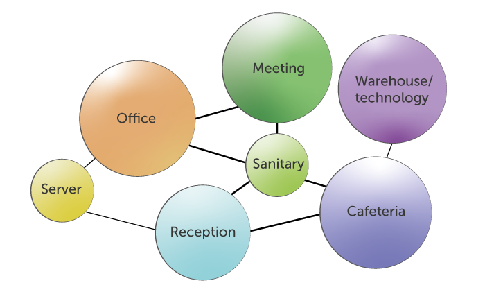
The design of a building begins with requirements planning. In this phase, the requirements and space requirements of functional areas are determined. Furthermore, the relationships of the functional areas to each other are determined. Thus,
for instance, the reception area is placed near the building entrance or toilets near the cafeteria. Functional area attributes resulting from the requirements include the number of occupants in the functional area, the type and quantity of sanitary taps, initial thermal load estimates, and volume flow rates for ventilation. At this step, a geometric model is not yet necessarily available. One challenge in the further design process is to reconcile the functional structure of the project with both a spatial and a technical structure. The obtained information should be documented in a machine-readable form as far as possible in the form of a digital room log book (see p. 16, The room log book as a tool in the design process). One should not be tempted into thinking that a room log book is documentation of the data of architectural rooms. Particularly in the early phases, it is of course permissible to abstract from the specific room and to plan in broader areas of similar use for the sake of an efficient working method. For example, one would address an entire office area instead of considering individual adjacent office spaces separately.
The path to three spatial dimensions
On the basis of a completed requirements planning, an initial geometric modeling can take place. To ensure that decisions are not already made here that prescribe too narrow a corridor for energy and sustainability targets, an approach is needed that introduces further dimensions step by step in coordination with the trades that create the structure.
The first dimension from an architectural perspective is represented by building heights and floor heights. These degrees of freedom are significantly influenced by the existing building stock or, in the case of new buildings, by client requirements, official specifications, and the size of the building window. From the point of view of utilization processes, the floor capacities can already be used as a basis for the initial division of functional units by area. From a MEP perspective, this information forms the initial design basis for vertical distribution concepts. Simple schematic considerations - in combination with empirical values - can be used to coordinate the location and size of equipment rooms and vertical access through supply shafts. Dimensioning of such space requirements does not require explicit geometric network modeling, but can be done purely on the basis of tabular totals.
Only when the second spatial dimension is added, does a certain degree of geometric design become necessary. However, it is also advisable here to start with a rough consideration in areas in order to keep the data model lightweight and to be able to react flexibly to changes. In this step, MEP determines the precise location of the equipment areas and supply shafts, and the distribution pipeline corridors are roughly routed from the respective equipment areas to the individual functional areas. This step therefore only determines from where and how the functional areas are accessed, but no explicit cable routing is modeled in the functional area. This has the advantage that changes to the concept can be easily updated in the pipeline corridor concept, since a pipeline corridor usually contains several pipes and detailed modeling in the functional areas is deliberately omitted. These two points lead to the number of objects in the model being kept small despite the high informative value, thus keeping the processing effort for tracking possible changes small. In this way, different versions can be created and compared with each other without much effort. Appropriate organization of the room log book data and the structural identification features allows for a transfer to the model and a subsequent summation to derive the dimensioning. Furthermore, the combination of room log book data and pipeline corridor concepts can be used to derive initial estimates of material quantities.
The procedure described above makes it possible to generate a high level of information about technical variants in terms of the location of equipment rooms and supply pipeline corridors in early phases with a manageable amount of effort and at the same time specify the necessary space requirements with sufficient precision.
1. Requirements planning
Description
- No 3D model available
- Determination of requirements and space needs for functional areas
- Determination of relationships of functional areas to each other
Available information
- Building type
- Number of individuals
- Load estimates
- Type and number of consumers
2. Functional concept
Description
- Creation of a concept body
- Location of functional areas in the concept body
- Creation of energy and system concepts
Available information
- Transfer of requirements from requirements planning tables to individual functional areas
3. Pipeline corridor concept
Description
- Location and space requirements of equipment areas of the individual trades
- Determination of shafts for supplying floors
- Determination of the pipeline corridors for supplying functional areas
Available information
- Equipment areas as source
- Functional areas as consumers
- Pipeline corridors with pipe types
- System topology
4. Model design
Description
- Creating rooms
- Converting pipeline corridors into individual pipes and air ducts
- Modeling of pipe routing in functional areas / rooms
Available information
- Requirements of functional areas are transferred to rooms
- Detailed load calculations
- Results of pipe and air duct network calculations
Avoiding conflicts and managing complexity
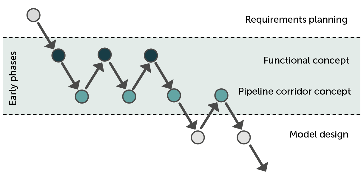
The advantages of a collaborative design approach in early phases become clear when looking at an example of a chronological sequence (cf. Figure 2). The process starts with requirements planning and step by step approaches a first rough concept for the functional-spatial and technical-organizational structure. The number of iterations and considered facility variants can be quite high here, since the conceptual pipeline corridor models are lightweight and flexible compared to conventional three-dimensional design. Only as soon as the rough structural design has been agreed, do the individual trades begin with the further detailing of the model design. For this purpose, too, a pipeline corridor concept is a good starting point for specialized modeling tools. If the information in the model is used consistently and continuously, it is possible to switch to a previous or subsequent step without much effort. For better clarification, Figure 2 shows the individual steps with a brief description and the available information.
Example application
Setting up requirements planning
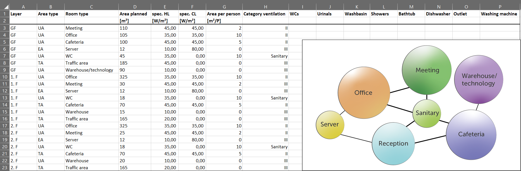
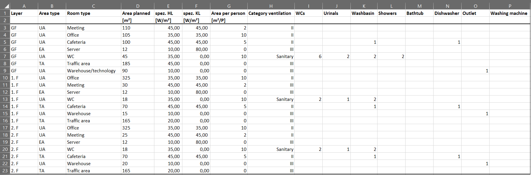
In order to clarify individual steps of the MEP design in early phases, we will explain them once explicitly with an example*. We consider a small office building that is to be equipped with 50 work places. Several meeting rooms, a cafeteria and, on the upper floors, a lounge area with a kitchenette are to be provided. Based on the initial requirements of the building owner and the basic conditions under building law, an initial tabular requirements plan is drawn up. A building window of approx. 40 m x 20 m with a three-story construction method can be realized for the planned property. Based on these basic conditions, functional areas for office, meeting, WC facilities, storage/technology, and traffic areas are defined. The space requirement for each type of functional area is determined for each floor. Furthermore, specific loads for heating and cooling, basic air quality requirements, occupancy density of individuals, and the number of sanitary taps can already be specified in this phase (see Figure 3).
*Please note that some simplifications have been made to clarify the basic methodology. In a real project, there may be much more information available at each stage.
Approaching the functional and pipeline corridor concept
A functional concept is to be derived from the requirements planning, in which the functional areas are located in an architectural concept body and an energy and system concept is outlined. The positions of the individual functional areas and the choice of system engineering have a significant influence on the size of the supply pipeline corridors. For this reason, the functional concept is drawn up in several iteration steps. For this purpose, a step-by-step approach to an optimal solution is worked out between the involved design parties through repeated exchange and adaptation of the concept proposals. The system concept specifies, among other things, the type of heating and cooling transfer system (radiators, panel heating, etc.). From this specification, further basic conditions are derived, e.g. the system temperatures and the differential temperature for the heating and cooling system. Loads (heating, cooling) and volume flow rates (ventilation, sanitary) can now be determined for each functional area from the information in the requirements planning. Together with the basic conditions of the energy and system concept, pipe dimensions can be determined, which in turn are required to dimension shafts and pipeline corridors.
In the first step of the functional concept, a concept body is used to define the building outlines and distribute the functional areas along the building grid on each floor so that the specified areas of the functional areas are roughly adhered to and the relationships between the functional areas are optimally coordinated. With this functional concept, the size of the equipment rooms is determined in a first pipeline corridor concept and again aligned with the functional concept. The functional areas planned for the equipment rooms are adapted to the estimated space requirements, which in turn again has an impact on the design of the other functional areas. In the next step, the positions and the required shaft dimensions are determined and again compared with the functional concept. If the positions of the equipment rooms and shafts harmonize well with the functional concept, the pipeline corridor concept is expanded and in the following design step the individual functional areas on the floors are connected to the shafts via pipeline corridors. Here, too, several steps may be necessary until an optimized solution is found for the functional concept and for the positions and dimensions of the shafts and pipeline corridors.
The individual steps in the example project
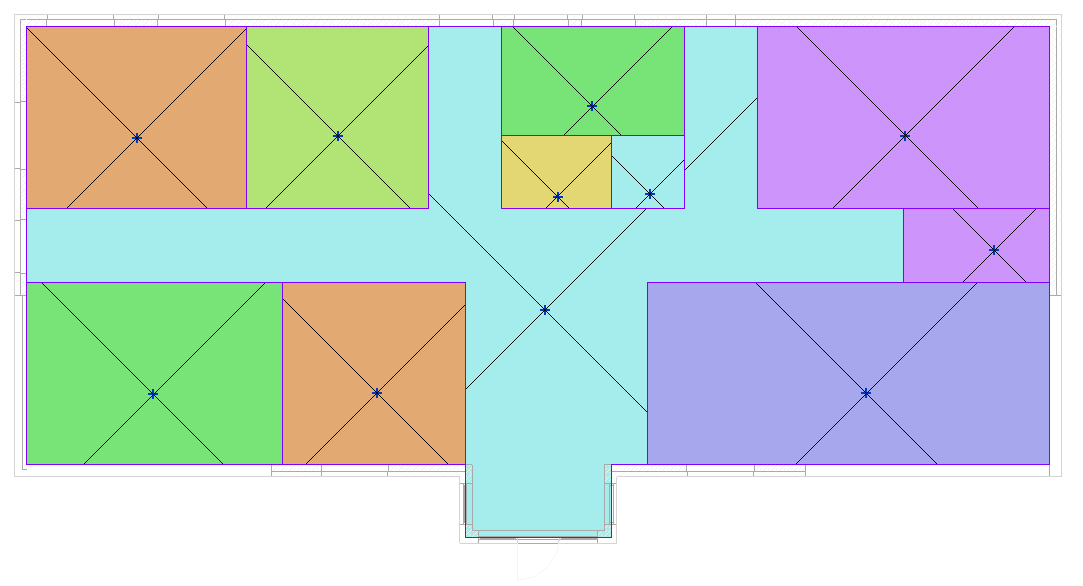
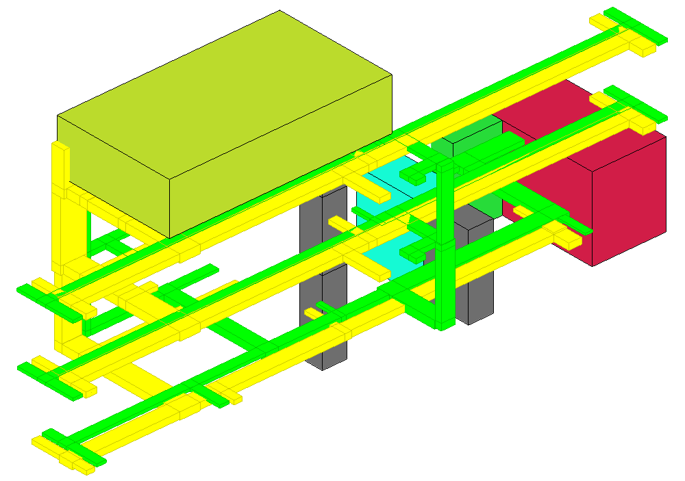
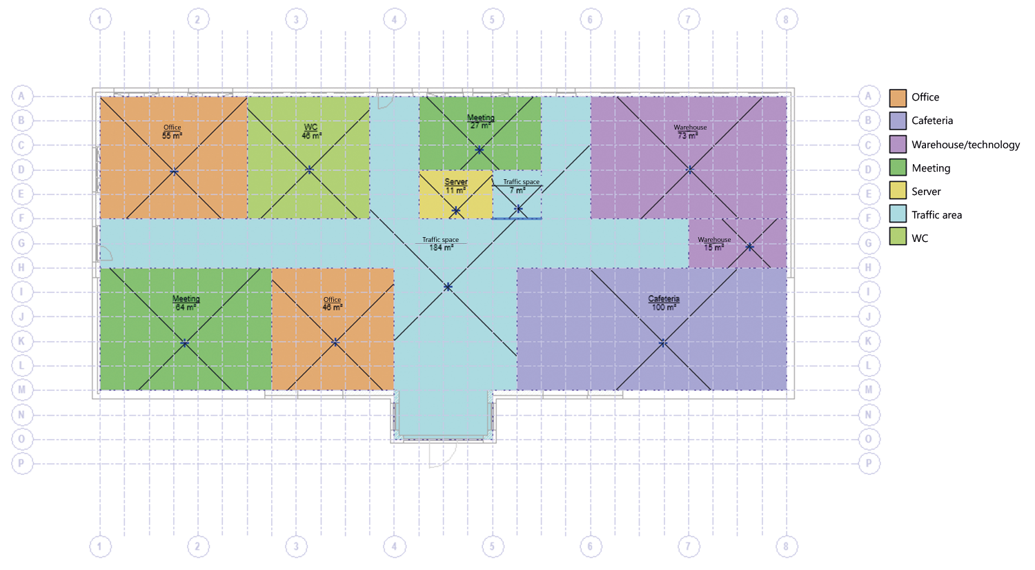
In the example building, the energy and systems concept envisages that the central units for heating, cooling, and sanitation are positioned on the ground floor and the ventilation center on the roof. Furthermore, it is planned to heat and cool the rooms with ceiling canopies. Figure 4 shows the functional areas of the ground floor in the concept body. By importing the requirements planning, the information is transferred to the functional areas and can be extended with the information of the system concept. With the information at the functional areas, a comparison can be made between the planned areas from the requirements planning and the actual areas in the model. Furthermore, the information can be used to estimate the loads that are used for dimensioning pipeline corridors and shafts. This is illustrated by the ventilation system. In the requirements planning, occupant density and air quality requirement (category) have been defined for the functional areas. With the values of the defined building type for the dilution of emissions (pollutant load), a volume flow rate can be determined for each functional area according to DIN EN 16798-1. For the sanitary rooms, the rules of the workplace directive are applied, based on the number of WCs and urinals, which were also determined in the requirements planning.
In order to start dimensioning shafts and pipeline corridors by summing up the volume flow rates, it should first be determined which system will supply it using the system concept for each functional area. In this way, several systems at different locations in the building or separate pipeline corridor routing can already be taken into account in the design at this stage. The system concept in the example provides that all rooms are to be supplied with supply and exhaust air by one system, so no separate summation is required for each system. Figure 5 shows the analysis and summation of the volume flow rates in the model. Since the system is located on the roof, the dimensions of the ducts for the shaft on the ground floor are calculated from the sum of the volumetric flows of all functional areas on the ground floor. The shaft on the first floor is based on the sum of the areas on the ground floor and first floor. The shaft for the second floor is based on the sum of all functional areas. In the model, corresponding pipeline corridor bodies are positioned at the locations where the shafts are planned. On the pipeline corridor bodies it is defined which types of piping will be carried out (supply/exhaust air, supply heating, etc.). With the summed loads and volume flow rates, the dimensions of the pipes of the pipes line corridor bodies are determined for all trades. For the ventilation shaft on the ground floor, duct dimensions of 450 mm x 350 mm are selected for the supply and exhaust air ducts with the summed volume flow rate of 2,732 m³/hr and the selected maximum velocity of 5 m/s. The definition of pipeline corridor cross sections with the positioning of the ducts and determination of the distances between the ducts results in one dimension for the duct bodies that is transferred to the model. The positioned and dimensioned shafts are compared with the functional concept. After several iterations, a solution is found that meets all requirements. Now, on this basis, the pipeline corridors in the floors from the shafts to the functional areas can be positioned and dimensioned.
![[Translate to Englisch:] Volumenströme der Funktionsbereiche für das Beispielgebäude](/fileadmin/_processed_/3/f/csm_abb-5_4253f0013b.png)
Transition to the model design
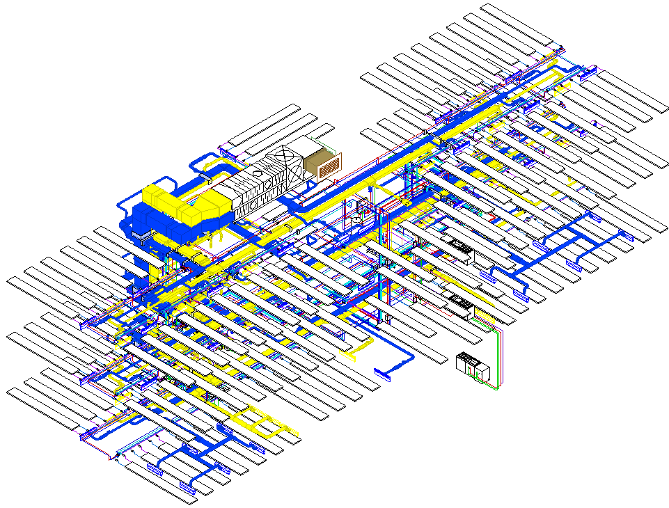
Based on the functional and pipeline corridor concept, a more detailed architectural model is developed that provides sufficient space for efficient pipeline routing. The functional areas are now divided into individual rooms in the model. The model is enriched with further information so that detailed load calculations (e.g. heating and cooling load) are possible. The calculated loads of the rooms illustrate a great strength of this method, namely the consistency of the information throughout the individual steps: The basic determination started with an estimated specific heating load. The specific power was used in the functional and pipeline corridor concept to determine the pipe dimensions and thus also the dimensions of the pipeline corridors. The detailed loads per room now available in the model design can now be summed up again for the corresponding functional areas, so that these loads can be used for a renewed optimization of the pipeline corridor concept. In general, more and more information is collected or further detailed in the model during the design process and each step builds on the information of the previous step. The increase in information density occurs without loss, so that information from previous design steps can be used at any time to iteratively approach an optimal design. In the example building, the paths of the pipeline corridors are generated (after the optimization of the pipeline corridor concept as just described) and the loads are placed and connected in the rooms (see Figure 7).
The pipeline corridor bodies are further used as a lightweight coordination model for collision checking. Here, they correspond to reserved space requirements that have been coordinated with the other involved design parties. If this subdistribution of areas of responsibility is strictly followed, elaborate coordination with other involved design parties only needs to take place if the reserved areas are penetrated, for example if not enough space has been provided for modeling unthreading. In this case, the critical areas can be specifically coordinated with other involved design parties.
Outlook
The integral design methodology illustrated in the example can already be implemented today with LINEAR Solutions for Revit. Future developments, however, will simplify the determination of the pipeline dimensions in the pipeline corridors even further. Methodically, this will be possible by using an analogy in which we regard equipment rooms as producers and functional areas as consumers that communicate with each other via shafts and pipeline corridors. In addition to placing pipeline corridor bodies, it will then only be necessary to define the transfer points and percentage of coverage of the media in the equipment rooms and functional areas. Based on this information, a system topology can be derived from a pipeline corridor concept and - taking into account basic technical conditions (e.g. simultaneities) - correctly dimensioned pipelines can be automatically assigned to each pipeline corridor segment. The pipeline dimensions are then - as before - the basis for cross-section design and the coordination of space requirements for technical media. In the future, the calculable pipeline corridor concept will make it even easier for users to help shape the early phases and quickly check intuitive assumptions made by those responsible for the structure. Quantity calculations based on room log book and pipeline corridor information are also significantly simplified, so that assessments of the costs and sustainability of the materials used can be made with little effort.