![[Translate to Englisch:] Die Erstellung des Strangschemas neu definiert](/fileadmin/_processed_/c/9/csm_Titel_Work-smart_Not-hard_57397e6a93.png)
The schematic diagram is a form of representation that is intended to show the functional relationships of technical systems and components in a simple, unambiguous and quickly comprehensible way. The added value of a scheme as an overview is particularly evident in large projects. Therefore, the creation of schemes is a service owed according to many national standards.
With the existing scheme generator, the LINEAR Solutions for AutoCAD offer a well-known and popular tool to create schemes quickly and easily. Since, of course, the model of the 3D system already forms the basis from which floor plans, sectional views, wall design, etc. are generated, the question arises as to why all the information that already exists in the model should be laboriously reconstructed to create a scheme. In view of the effort required for the separate creation and the transfer of each change from the 3D model to the schemes, it is therefore not surprising that the need for an automatic generation of a scheme based on the 3D model has already been frequently expressed to us.
In this article, we would like to take a closer look at the challenges involved in implementing an automated process for creating schemas in Revit, but also at the associated benefits in addition to the workload reduction.
Definition: Schemes
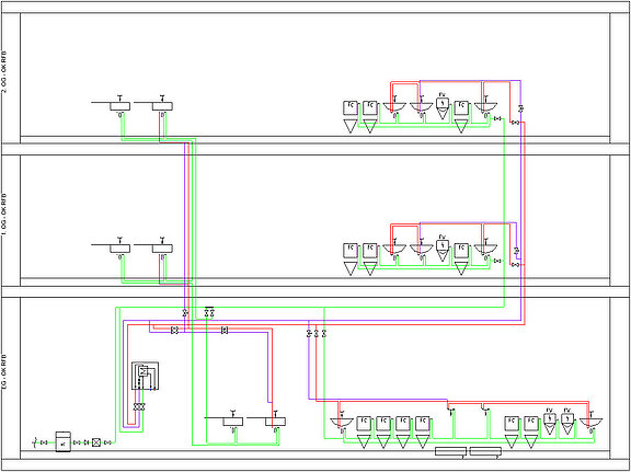
In a scheme, a branched, three-dimensional pipe network is to be represented in a simplified, two-dimensional view. For this purpose, one dimension is folded into the drawing plane, neglecting the scale of the horizontal pipes. The height position of pipes, components and built-in parts is then illustrated proportionally. Furthermore, pipes that would overlap in a sectional view are pulled apart in the schematic and arranged in parallel. Bends and pipe offsets, on the other hand, are neglected. The storey levels form the basis and the frame of the drawing view, whereby the scheme with the representation of the functional relationship of the technical systems and components can be seen simplified as the union of a vertical building section view.
To meet the aforementioned requirements, attention must be paid when creating a scheme to ensure, on the one hand, that the consumers, fittings and built-in components as well as their pipe connections are physically correct - this is the basic prerequisite for a technically correct scheme. To obtain an easily readable scheme, however, the “layout” must also be suitable: A clear spatial location of the components without unnecessarily long pipes and as few crossings as possible enables the viewer to quickly see relationships in the system.
If you take a closer look at this subject and also scrutinize basic details, you can see that the creation of a scheme is not quite as trivial as one might initially assume. Drawing a scheme requires a stringent and focused approach in order to create it correctly and legibly - not only on the first time.
The scheme in the current design process
Even if a scheme may seem out of place in a project modeled in 3D, it absolutely belongs to the planning documents at the latest for large projects or complex systems. To recognize the technical correlations directly from a 3D model would require a considerably greater investment of time. So, it is not surprising that the creation of schemes is a service owed according to many national standards. Here, a distinction is made between the functional scheme and the scheme.
In the preliminary design, most national standards require a functional diagram of the technical systems. In this case, the focus is on the basic functions and relations of the systems. The aspect of spatial location becomes secondary, also due to the fact that the floor plan is still “flexible” at this point.
In the further design phases, the schemes need to be updated and detailed. In later phases, schemes are finally required, in which the influence of the architecture on the pipe and duct routing in the form of room arrangement and the sequence of the consumers to be connected can be seen.
Due to the dynamics of the design process, it is necessary to repeatedly update the schematics until the end of the design phase. Among other things, this can result from changes in the spatial arrangements in the architecture. However, such adjustments are usually associated with considerable effort, since all documents have to be adapted.
The creation of a scheme with Revit is possible in principle, but currently very cumbersome and time-consuming, because basic functions for the integration of schematic design in Revit are missing. With AutoCAD or the scheme generator from the LINEAR Solutions for AutoCAD, practicable workflows have been established. Nevertheless, the previously mentioned points led us to the conclusion that there is a great incentive to think about a practicable solution in Revit, which on the one hand should make work easier and on the other hand makes a second design platform exclusively for schematic design superfluous.
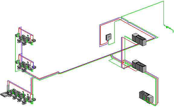
Deriving the scheme from the 3D Model
A finished 3D model already contains all the information needed to create a scheme. This is the basic prerequisite for the automated creation of a schematic diagram from the model. What may sound like a simple task at first, however, poses several challenges during implementation, because apart from the geometric problems to be solved, rules for schematic generation must first be defined, which the experienced designer now intuitively implements and observes during drawing. Writing the code to achieve the “performance of abstraction” for the conversion of the drawing is an exciting challenge. However, a practical implementation of an automated approach is currently nowhere in sight on the market. With the upcoming release, LINEAR is now taking the first step in this direction. Thus, we enable the creation of schemes for potable water networks without further preparatory work at the push of a button. In addition to reducing the initial effort required to create the scheme, this feature offers many other advantages.
Analyzing the model and layout
With the help of defined design rules, the 3D model is analyzed, and the sections and components are placed in a physically correct way, considering the relative height in the storey and in the corresponding connection sequence.
When placing the consumer groups, the program analyzes how to create a scheme that is as compact as possible in order to avoid unnecessary free spaces between usage units. This space optimization not only makes for a tidy look of the plan, but may also save you post-processing to avoid a page break in the end.
Multiple systems
Automatic detection examines hot water and circulation systems in addition to the cold water system. Systems with centralized or decentralized water heating are also detected and mapped in the scheme. Here, thermally optimized positioning of hot water pipes above cold water pipes is also taken into account.
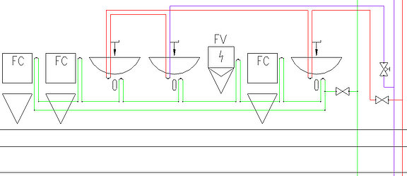
Pre-wall installation
Furthermore the pre-wall installation is adequately mapped. Whether in-series installations, closed circular pipes, flow dividers or looped-in connections: All these special features are derived from the model and correctly transferred to the schematic (see Fig. 3).
Link between model and scheme
During automatic generation, a bidirectional link is stored between the components in the 3D model and the equivalent symbols in the scheme, thus enabling easy navigation between each other. The link also greatly simplifies the tracking of the scheme. New calculation results from the 3D model can be automatically transferred to the schematic for updating the labels accordingly.
Symbol library
With the pre-installed symbol library, a selection of symbols for the most common parts already exists and therefore the conversion into a scheme can be started directly. Furthermore, it is possible to exchange symbols without losing information or the link to the model. And finally the symbol selection can easily be supplemented by user-defined symbol families and then exported and stored e.g., as company standard in the network.
Post-processing
To be able to put the finishing touches to the scheme based on subjective ideas, a number of functions are provided to allow easy editing of the derived schematic drawing.
Summary and outlook
Since we do not want to withhold this tool from our customers any longer than necessary, we will publish the first implemented discipline Potable Water immediately after completion. By the way, previews will already be available in March at the ISH 2023 in Frankfurt. This powerful tool represents a first step towards redefining the creation of schemes. We are very eager to hear your feedback!