![[Translate to Englisch:] Neues aus der LINEAR Entwicklung](/fileadmin/_processed_/f/6/csm_Titelgrafik_V23.2_c16b5efadd.png)
We dedicate separate articles to two of the most important news: The feature called “Fabrication” (blog article "Fabrication or Design 3D?") and the “Scheme Converter” (blog article "Work smart, not hard!"). Both are really exciting innovations that are sure to put a smile on the faces of our existing customers and those who want to become customers.
No less exciting, however, are the other innovations that these releases have brought with them. Some of them can simplify your work so much that you will never want to do without them again. As an example of the range of innovations, I would like to present my two personal favorite features.
Revit-TGA 2 AVA
Have you ever tried to extract a quantity take-off from Revit MEP models that can be processed directly in software for tendering, awarding, and billing? We have! Since we wanted to answer the question of what we can do to better align a model-based quantity take-off with the workflow of tendering, awarding, and billing, we explored the current software landscape. Our evaluation of the workflows has a rather mixed result: Starting from the speed of the process, through the workload and the quality of the results, and ending with “doesn’t work at all”, the - mostly IFC-based - workflow could not convince us. Consequently, we had to come to the conclusion that there is not a single workflow yet that works really well.
The process - or detour - via an IFC exchange file is of course an obvious approach, at least in the Open BIM workflow. The fact that the determined quantities are additionally visualized in an IFC viewer in the software is a side effect. Nevertheless, there are certainly few Revit users who can generate a correct quantity take-off from their model “at the push of a button”. Conversely, there are hardly any cost estimators who can elicit a tender-ready quantity take-off ad hoc from their tendering software using any IFC model. Even if the IFC model has been exported by the planner in a way that is “fit for quantity take-off”, does an estimator really want to use the corresponding quantity take-offs from an IFC model to visually check the plausibility of the quantities in the viewer?
This will certainly not be a new favorite task for anyone, especially since it consumes a lot of time. Our experience and the exchange with users and cost estimators have led us to develop a solution ourselves that does not impose an additional workload on our users. For this purpose, we considered the desired result first and then the task itself, because in the end, software for tendering, awarding, and billing does not need IFC models in the BIM age, but primarily a reliable quantity take-off from the CAD model, of course compliant with the Construction Tendering and Contract Regulations and determined according to the corresponding guidelines. The proven GAEB (XML) format, which all relevant programs can handle for years now, is ideal for transferring this list.
The challenge we faced was to enable the user to determine reliable quantities with as little effort as possible.
Whereby the requirements “low effort” and “reliability” initially seem like opposites, especially if the Revit models contain third-party or self-created families. The key here lies on the one hand, in the classification of components, which is an integral part of the LINEAR Desktop framework. If you know which components are to be assigned to which sub-services, a lot has already been gained. Since information for generating the service description or even for classification into cost groups can be available in a wide variety of parameters, an easily configurable use of these model parameters is also necessary.
The solution therefore consists of a dialog for a quantity take-off that enables the configuration of the parameters and at the same time presents each adjustment in the result in an immediately comprehensible way.
The initial effort for the parameter configuration remains manageable, also because LINEAR already provides suggestions for the parameter settings for individual partial services. In this way, not much effort is required, even for the first model. For further models, the effort is reduced to zero if one works with a similar set of families in each case.
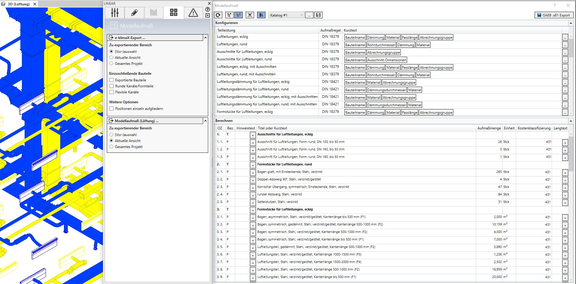
For this first version of the module called “LINEAR Model Measurement”, we will initially limit ourselves to the ventilation trade. In the meantime, this feature is being developed for the other trades and furthermore for the slot and opening planning and will reach you with the next feature packs.
Set different material automatically in shaft
This corresponds to one of the user requests that are repeatedly expressed. Not absolutely necessary, but already very helpful! Because what is still easy in the schematic becomes very complex in 3D models: Namely, the definition of different materials for basement, riser and storey pipes by manually assigning the material to the drawn pipes. This changes with the V23.2, because the program can now automate the assignment in large parts.
For systems which are planned in Revit or with the LINEAR Design 3D family under AutoCAD, the network calculations can now take over the material information of the used pipes/ducts and assign them to the pipe systems of the network calculations. However, if you are carrying out your design with neutral material throughout, e.g. to maintain neutrality in the model, or because you are designing the networks using the single-line method, the task of manual assignment remains.
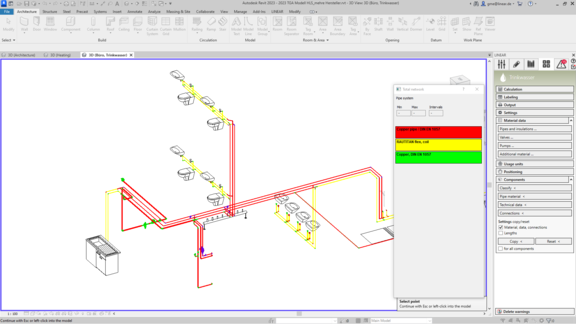
This is where the new topology detection provides a solution. The calculations automatically recognize the areas of (main) distribution, shaft/pipe run and storey/connecting pipe in the planned system. This works in all network types, regardless of whether it is a schematic, a 2D floor plan or a 3D model.
After detection of the topology, the calculations now always offer at least three automatically generated entries in the table of materials, corresponding to the detected areas. In potable water pipe networks, a further breakdown is made into hot and cold water, since the insulation will be different in both cases.
So all you have to do, if you want to use different materials in the areas, is to enter the desired materials for pipes and insulation in the table. The appropriate materials will then be used when dimensioning the pipes and insulation. The materials for creating heating and sanitary connections are also determined - according to the pipe types and the installation situation - and included in the material output. Of course, the manual assignment can be carried out as usual and is valid even if the automatic process would determine something else.
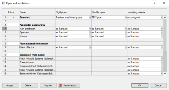
Last but not least, the restriction to “One pipe manufacturer (+ any neutral material) per network” has been removed with this change. So you can specify a different manufacturer for each entry in the material dialog.
As you could read here, it sometimes takes a little longer before suggestions from customers can be turned into reality. But this happens regularly. This suggestion is just one of several that will be realized with the two feature packs. I would like to encourage you to continue to send us your ideas and suggestions for improvement - in a new format: The “Idea Channel”. The main advantage of this format is that you can vote for ideas that already exist and in turn put your own ideas to the vote. This way, your ideas can quickly gain weight.