
How it all began
16 years have passed since Autodesk first introduced the Revit platform. The idea – revolutionary at the time – of creating parametric models also in the field of construction had been born a few years earlier, because Autodesk had a vision at the time which is known worldwide today as BIM. A short time later it became clear that, with Revit, people wanted to model not only the architecture, but also the entire building – a reason for the “closed BIM“ debate of today.
How did the desktop for revit come about?
At that time we observed it with mixed feelings and wondered whether Revit becomes a competing product or an additional platform for our solutions. At first, we assumed that model construction would remain an Autodesk matter, and we would mainly take responsibility for model analysis. In other words, architectural analysis for heating and cooling load calculation purposes and pipe network calculations in all disciplines.
However, this point of view did not last long. Less than a year later, Autodesk approached us with a request to develop family and construction tools for the German speaking markets: LINEAR Routing & Content Tools were born. It became increasingly clear that, for the sake of a “generic” platform that could be used worldwide, Autodesk was not prepared to delve into the details of implementing innumerable standards and calculation methods. As such, solutions would have to continue to be developed by “solution providers” – which is how we see ourselves .
The fact that a simple – and perhaps even comprehensive – tool collection cannot be viewed as a "solution" became clear to us, because as we developed many function extensions for Revit, they didn't really "communicate with one another". So we needed a “framework” – a basis on which all our tools can rest. A basis which also takes responsibility for the central management of parts of buildings, storeys, system types, views, etc. A basis which would also provide a common user interface for our solution – for standardized and intuitive operation for all individual components. A basis in which workflows could be depicted: Work steps in meaningful sequences, permanent access to frequently-used functions, and communication with all participants incorporated in one’s own processes.
All these requirements on a solution and much more besides led to our product for you: The LINEAR Desktop for Revit.
Tools fir the early design phases
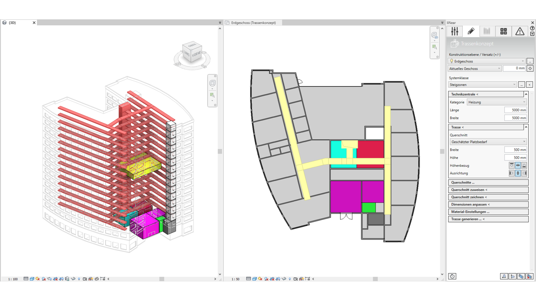
Integrated design means that, even in the early design phases, all the players work together on the building concept. With our tools for the design, dimensioning and placement of equipment rooms and supply pipeline corridors, already in the preliminary design stage you are able to optimize the integration of the MEP systems in collaboration with other trades. The resulting initial effort is more than compensated in subsequent design phases through a reduction in points of friction.
Pre-dimensioning of equipment rooms
New tools are available for the dimensioning and placement of equipment rooms. With these tools, you can determine realistic space requirements for the equipment rooms and coordinate this with other participants early on. The order of the day here is “Conflict prevention, not conflict resolution”. The space required by the equipment rooms for the individual trades can optionally be determined quickly and easily with the entry of a small amount of data, or specified based on experience. The equipment rooms can then be placed in the model as Provision for Space (an element of the IFC 4.0 standard) and the space requirements compared with the available space in a conceptual architectural model. The export of the equipment rooms by means of IFC enables quick and easy coordination
Defining supply pipeline corridors in the predesign
The pipes for the individual trades run as a pipeline corridor from the equipment rooms to the consumers. With the pipeline corridor function, these can be constructed easily. Subsequently, the cross-sections are defined and assigned to the individual pipeline corridor sections. Adjust dimensions is a quick and easy way to adapt the space requirements of the pipeline corridors to the assigned cross-sections. Once the pipeline corridor concept has been coordinated with all parties involved using IFC, the pipelines can be generated automatically and used as the basis for further design phases.
Tools for the model organization
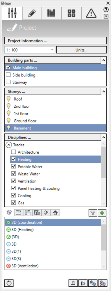
View control
An important aspect of your model organization is the view control. Depending on storeys, discipline, design phase, building part, etc., views in Revit display in a given way (floor plan, ceiling plan, 3D-view, sectional view etc.) a given part of the model.
To reconstruct this over and over again manually for the many different views that are necessary in a Revit model doesn’t make sense. Revit therefore offers the option of creating view templates that already have default settings. In itself a good idea, were the templates not so inflexible. If, for example, one has switched on the pipe insulation in the template it is difficult to switch it off in an individual view. This is only one example of many, which leads to an immense quantity of templates and is not very helpful, in our view.
The next point is the creation of new floor or ceiling plans. Anyone who has already worked in Revit is well aware of what it means to do this for numerous storeys and multiple disciplines, etc..
And not least the selection of the correct view. How do you organize the view tree? What parameters do you attach to the views, to be able to group and sort them? How many folder levels do I want to have in the view tree? In smaller to medium-size buildings, this may still be acceptable, but what is to be done with hospitals or office buildings with several large building sections, different storey heights, etc.? View control in Desktop handles all this.

Take advantage of...
- the minimum necessary selection of flexible view templates.
- visibility control by fading in and out levels, disciplines, systems and individual details, such as pipe insulation, with only a single click.
- lean project templates, that use just-in-time loading.
- automated naming for views (optional).
- view creation for several storeys in a single work process.
- creation of personalized views for your work in a “Worksharing-process“ (for example to filter out all other views).
- a clearly arranged view tree – suitable views are always offered for selection, based on the building part, storeys, discipline and type of view.
- separation of task views and views that are to be used in plans.
- convenient creation of working sections with rapid access.
- simple switching on and off of entire storeys, even in 3D-views.
- transfer of view properties to any of numerous other views.
In summary, it can be said that there is nothing to worry about on the subject of views any more. It simply works.

Storey tables
Revit building models use levels as the basis for all components belonging to the building. Levels can also mean storeys, but they can also be simple work levels for the height of a prefabricated floor or a suspended ceiling. Maintaining an overview in such cases – particularly for building sections with varying storey structures – often represents a challenge. For this, the storey dialog in Desktop helps provide an overview and maintain it as the project processes.
Take advantage of...
- the automatic adoption of levels defined by the architect into your MEP model.
- a change management and be informed when the architect makes changes, so you can decide how to respond.
- a logical separation of work levels and storey levels.
- an administration of work levels in relation to storey levels (e.g. finished floor level: +150, BEC: -200).
- the option of splitting your model, e.g. into building sections (the appropriate storey table for each building section).
- the storey tables as an information center for view control and for determining the construction height
Disciplines and systems
Part of the structure of an MEP model is the assignment of all components to disciplines (trades) and systems (media).
Revit supplies a classification of components and connections which is frequently inadequate for MEP use cases.
Here, Desktop affords the option of precisely depicting MEP requirements by allowing you to manage disciplines and systems.
Take advantage of...
- the opportunity of creating your own systems.
- the assignment of these systems to specifically created disciplines.
- the adaptation of existing systems and defining your own colors, names, line thicknesses and visibilities.
- systems completely intuitively when constructing your lines and pipeline corridors.
- disciplines, to always be offered only the right tools.
- disciplines for the organization of your views.
A MEP model structured in this way is not only important for the view control but also analysis programs and data exchange with other participants benefit from it.
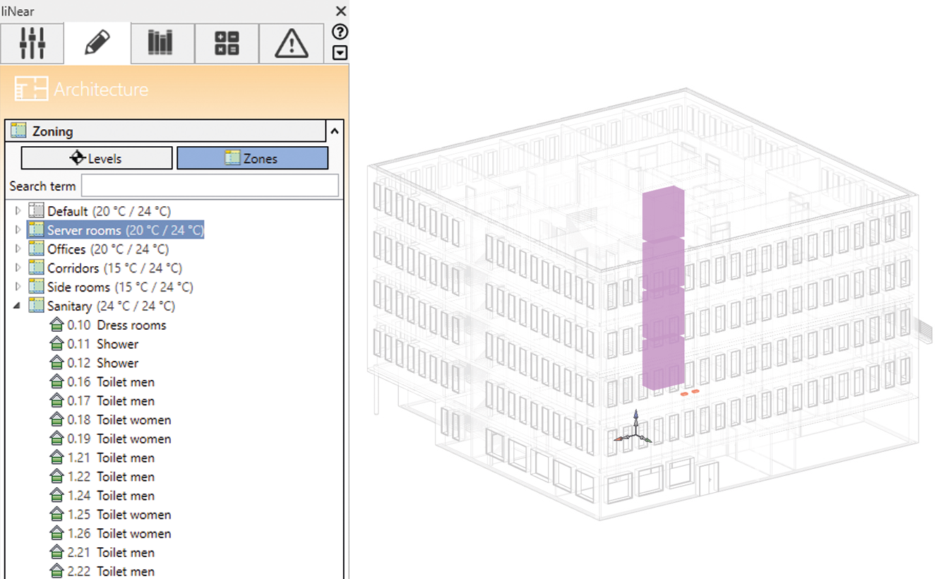
Zoning
Among others, grouping spaces into zones is helpful for simple determination of target temperatures for cases of heating or cooling. In Revit, basic zoning functionality already exists. The zoning dialog in the LINEAR Desktop adds ideal management and a perfect overview to it.
Take advantage of...
- the Drag&Drop function to structure spaces into zones.
- templates for frequently used zone types.
- clear presentation of groups, with and without storey referencing.
- visualization of spaces and zones in the model for a quick overview.
Adoption of architectural rooms in MEP spaces
For a frictionless workflow in a BIM process, both architect and MEP designer each need a “personal space” to store their specific information. Naturally, it makes sense when creating MEP spaces to initially adopt values such as the architect’s room name and number, but the MEP designer usually needs further “spaces”, e.g. in shaft areas. Desktop offers multiple options for these tasks.
Take advantage of...
- an individual or fully automatic creation of MEP spaces.
- the option to select which data is adopted from the architect.
- the option of assign shaft areas with MEP spaces.
Tracing an underlying 2D-architecture
You do not have access to the architect’s 3D-model, but you still want to benefit from the advantages of the 3D model design?
Take advantage of the architectural features of the LINEAR Desktop, to create your own 3D-model based on the 2D drawings.
Take advantage of...
- simple features to “trace“ walls, windows, doors and ceilings.
- accelerated model construction through the combination of “2D-measurements“ and preset component heights.

Families for the model creation
Components are the core of a building model, and are consequently termed “Families” in Revit because they are often parametric and thus not only one component, but represent an entire component family. Requirements on the families increase with users’ growing experience and increasing standardization. It is thus all the more important to use high quality families that evolve constantly with the state of the art.
LINEAR Desktop delivers both neutral as well as manufacturer-specific high quality families and provides you with convenient features for managing and using the families.
Take advantage of...
- parametric families for manufacturer-neutral design.
- the complete and up-to-date catalogs of our industry partners for manufacturer-specific design.
- families produced from our dimensioning solutions.
- independently created or third-party families through seamless integration in the Desktop library.
- configurators for manifolds, tanks, floor heating/cooling, radiators and dwelling stations to generate individual families.
- intelligent placement functions for swift and clean integration of components in your model (place on grid, replace individually, replace all, etc.).
Tools for model construction
Draw pipes/ducts
In Revit, pipes, air ducts and electric cable trays are organized differently from other components. They are defined as the link between a set of families (pipe/duct type + fittings) with a corresponding set of “building rules“ (routing presets). With LINEAR Desktop, these pipe and duct classes are reloaded quite conveniently only when used – this eliminates holding or administering pipe classes in template files.
In addition, the function works directly with storey management. The height level of the pipes can be selected very easily (e.g. “100 mm BEC“ starting from the selected storey).
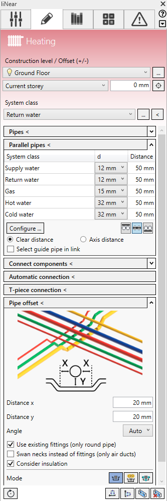
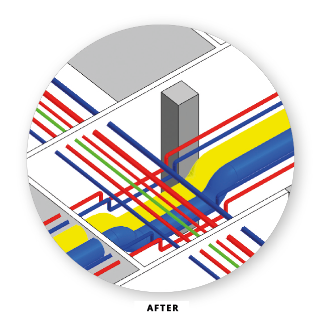
Parallel pipes
The “Parallel pipes” function is the ideal addition to “Draw pipes/ducts” for designing bundles of pipes.
Take advantage of...
- specifying clearances or axis distances between pipes/ducts.
- reusable definitions of pipe bundles with pipes and ducts from different disciplines and system classes.
- manufacturer/pipe material and dimensions within the configuration.
- presets for insulation materials and the corresponding thicknesses.
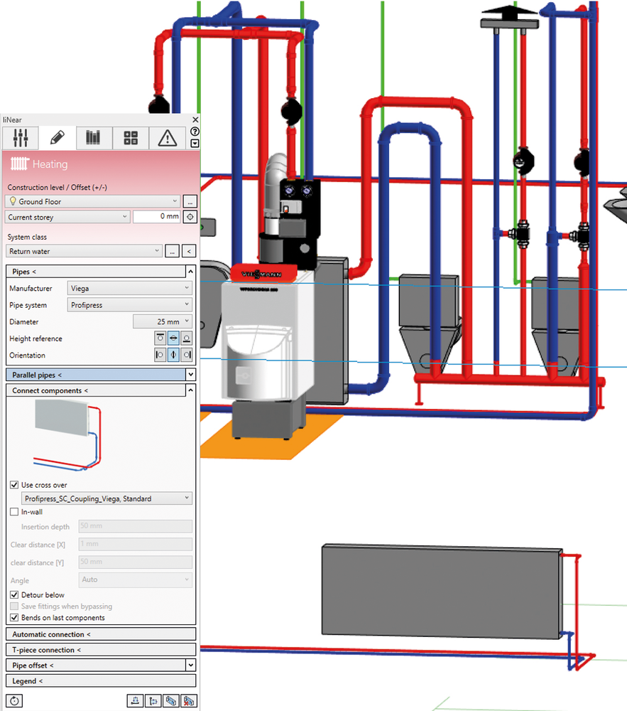
Connect components
Anyone who has already connected a radiator or even a toilet with a downpipe to manifold or collective pipes will definitely appreciate the “Connect component” function. The command provides you with support for a wide range of connection variations. Here are a few examples:
Take advantage of...
- connecting up outlets, including automatic integration of built-in parts in the connecting pipe (e.g. sound absorbers or throttle valves).
- connecting up components to cold and hot water pipes looped in with ear elbows or alternatively by T-piece connection.
- taking into account the pipe sloping when connecting drainage components.
- possibilities of offset for collision-free connection of radiators (surface or flush-mounted).
- simultaneous connection of multiple components in a single work step.
- automatic placement of a bend at the last component of a pipe run (optional).
Connect
Standard connections of two pipe ends can naturally also be created with Revit on-board resources. However, the Desktop’s connect function is more flexible – particularly in situations that allow more than one solution. Desktop analyzes the situation and provides you with all sensible alternatives for selection.

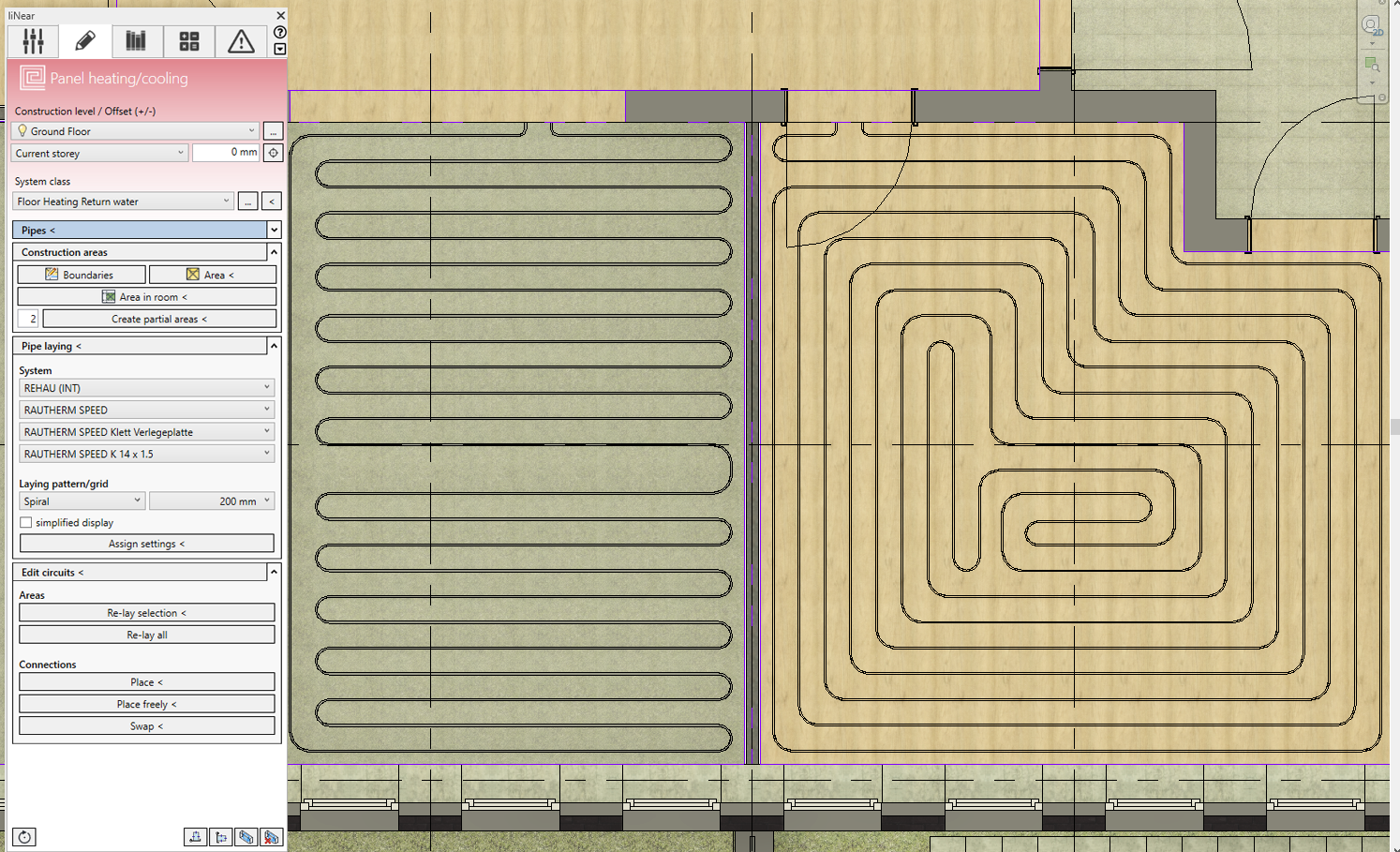
Panel heating/cooling discipline
One of the harder nuts to crack for a parametric modeling design is the high degree of individualization when modeling panel heating/cooling. In a single building, there are hardly two rooms which can actually use identical circuits. Exceptions, at most, include completely identical storeys.
For this challenge we have devoted a separate discipline – panel heating/cooling.
Take advantage of...
- automatic laying in space shapes of any complexity.
- the selection of alternatives for splitting the circuits.
- data from the leading manufacturers of panel heating/cooling systems.
- the selection of different degrees of detailing: Either only circuit areas with connections or precise pipe laying in spiral or meander form.
- the adjustment of the connection location of the circuits with a single click.
- the connection of the circuits to the manifold via supply pipes.
- bidirectional connection for calculating panel systems in LINEAR Building. Panel systems designed in LINEAR Building can be placed directly in the model, and panel systems designed in the model can inversely also be calculated directly in LINEAR Building and matched hydraulically.
Tools for coordination
Not only since the introduction of the BIM methodology has it been important to coordinate design processes across all trades. Principally, with increasing digitization, this can be accomplished more easily – but nevertheless the exchange of digital models is not sufficient. It requires special tools, with which coordination processes can be represented in a practicable manner.
Void planning (Slots and openings)
There is hardly a design task that requires more coordination than the slot and opening design. With its influence on statics, optics and function, as a rule all those participating in the design have something to say here. We offer you the right tools to integrate your design in this process.
Take advantage of...
- the LINEAR collision check to calculate all collisions between individual or multiple disciplines with the architecture.
- the manual or automatic placement of suggestions or placeholders for slots and openings on the basis of the collision check (so-called PfVs - “Provision for Voids“).
- the rule-based or even retrospective manual summarization of individual openings.
- automatically generated labeling texts with reference to the architecture.
- the forwarding of your suggestions (PfV) for checking and further processing in IFC and/or BCF format.
- the coordination of opening approvals and change requests from design partners with their current design.

LINEAR Void Manager – Freeware für Architekten/Statiker
Um die Koordination der Schlitz- und Durchbruchsplanung möglichst einfach, sicher und komfortabel zu gestalten, stellen wir Ihnen bzw. Ihren Planungspartnern ein kostenfreies Revit-AddIn zur Verfügung – den LINEAR Void Manager.
Nutzen Sie (bzw. Ihr Architekt) ...
- die im LINEAR Desktop generierte BCF-Datei für die Prüfung, Freigabe und weitere Bearbeitung aller Schlitze und Durchbrüche.
- die Navigationsfunktionen des LINEAR Void Managers, um jeden Vorschlag zu sichten und dann entweder zu akzeptieren oder – ggf. mit Kommentar – abzulehnen.
- die automatische Umwandlung akzeptierter Durchbruchsvorschläge (PfVs) in „echte“ Durchbrüche im Architekturmodell.
- die Möglichkeit Bauteile (z. B. Wände) zu sperren oder komplett freizugeben und damit alle enthaltenen Vorschläge zu akzeptieren.
- die Rückmeldung an den Ersteller oder weitere Planungsbeteiligte ebenfalls via BCF und IFC.
Aufgaben- und Reportmanager
Der Aufgaben- und Reportmanager ist der zentrale Ort für alle im Planungsprozess anfallenden Meldungen und daraus resultierenden Aufgaben.
Nutzen Sie ...
- die geordnete Übersicht aller automatisch (z. B. aus den Rohrnetzberechnungen) oder manuell angelegten Aufgaben und Reports.
- die Statusanzeige jedes Tasks zur Überwachung des Bearbeitungsprozesses.
- die Navigation per Doppelklick zum „Ort des Geschehens“ und Anzeige aller beteiligten Bauteile.
- die Möglichkeit, Aufgaben durch Screenshots, Fotos und weitere Beschreibungen zu detaillieren.
- die „Chatfunktion“ zur Abstimmung mit anderen Planungsbeteiligten unmittelbar innerhalb der Aufgabe.
Klassifizierungs-Manager
Mithilfe des Klassifizierungs-Managers haben Sie die Möglichkeit, Modellinhalte anhand unterschiedlicher Aspekte zu strukturieren, sowie projektweit einheitliche Standards einfach umzusetzen.
Nutzen Sie ...
- die Klassenzuweisung nach IFC 4.1 und IFC 2x3 für einen optimalen IFC-Export.
- die Zuweisung von Bauteilen zu Kostengruppen (DIN 276, ÖNORM B1801-1, SN 506 511).
- die Möglichkeit weitere Klassifizierungssysteme zu ergänzen.
Construction design
The original concept behind Revit – total parametric building design – never envisaged design down to the last detail. For performance reasons, and to “keep the modeling tools simple”, the detailing necessary for construction design was not envisaged. As such, the concept of connection technology (flanges, screw connections, plug-connectors, etc.), for example, was not implemented.
To be able to use Revit as a complete design tool, however, one would naturally also want to use it for the final construction design. From the current perspective, this is certainly possible, as there are now systems which can be used very simply and without loss of performance. These are also included in the LINEAR Desktop.
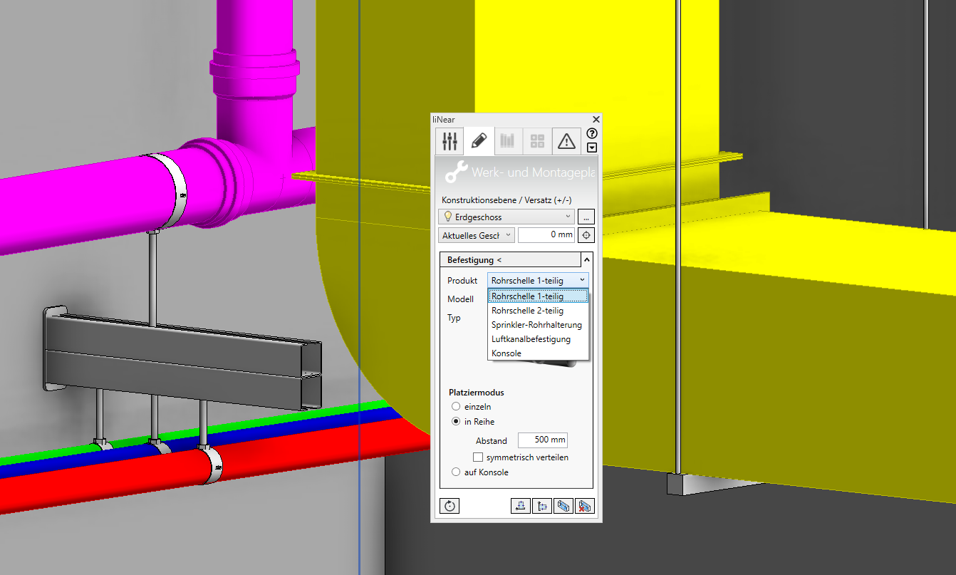
Fixations
A task which cannot be neglected in the design process is the design of fixations – after all, the space it takes is not insignificant. Complete this task with simple tools.
Take advantage of...
- the placement of clamps, consoles and fixations for air ducts or electric cable trays.
- the automation to determine different types and dimensions, or decide manually.
- the placement modes “single”, “in line” or “on console“.
- generation of complete parts lists for fixations.
![[Translate to Englisch:] Flanschverbindung](/fileadmin/_processed_/9/b/csm_Abb_14_Flanschverbindung_e11da1011c.png)
Section/delivery lengths
The division of air ducts into section lengths is necessary at the latest when it comes to the ordering of materials for installation.
Take advantage of...
- the automatic splitting of the selected pipes into fixed section lengths.
- the program logic which also allows cutting fittings to length, to avoid lengths being left over.
- the allocation of previously available duct grills to newly produced duct parts.
Item numbering
A task that is equally essential for the ordering process is the allocation of item numbers. The Desktop also provides this.
Take advantage of...
- the automatic allocation of sequential item numbers for selected pipe runs or entire systems.
- different selection modes, and determine the start of the numbering according to each mode.
- the option of assigning identical parts the same number.
- your own prefixes, to generate different number groups.
Draw flanges
The absence in Revit of logic for connection technology translates into tiresome contortions when it comes to build in flanged fittings in pipelines.
Take advantage of...
- the installation of flanges directly with matching counter-flanges in the pipe (fig. 15).
- automatic installation of flanges everywhere that they are absent.
- generation of complete parts lists.
Summary
With its multitude of workflow-oriented features, LINEAR Desktop is an example of how you can take a generalized platform for parametric model development like Revit and produce a perfect solution, customized to satisfy the requirements of the MEP design.
Compared to other tool collections, Desktop can be used as an ideal entry into a scalable overall solution. Models created with Desktop can be the basis for building analysis in an ongoing process. And all MEP installations serve as a basis for LINEAR network calculations, including redimensioning.
As such, Desktop is the core unit of the LINEAR product family – an indispensable tool for any MEP designer. It is currently available as entry level offer for less than € 1,000.00 (see offer on page 2).