![[Translate to Englisch:] Revit Mythen Titel](/fileadmin/_processed_/d/6/csm_titel_webseite_neu_e27362976a.png)
Myth 1: BIM objects have to be parametric
As a Revit newcomer, you learn to particularly appreciate one feature of the new platform: its parametrics. You quickly get the impression that anything not parametric contrasts to the idea of BIM and is therefore no longer up to date. But is that really true? Now, in order to answer this question, it is necessary to distinguish which type of component is dealt with in which planning phase. If generic families are used to design first, then suitable parametrics on components is desirable. If components are able to dynamically react to changes in position or dimension, they allow for a very comfortable design process. However, it is exactly this flexibility that is no longer wanted when it comes to finalizing the design or even introducing manufacturer-specific components into a more detailed model. At this point at the latest, it can be considered as a feature if the parameterization is limited to specific products. Not all components are custom-made. Therefore, it makes sense that only products that can actually be ordered can be inserted.
Useful parametrics
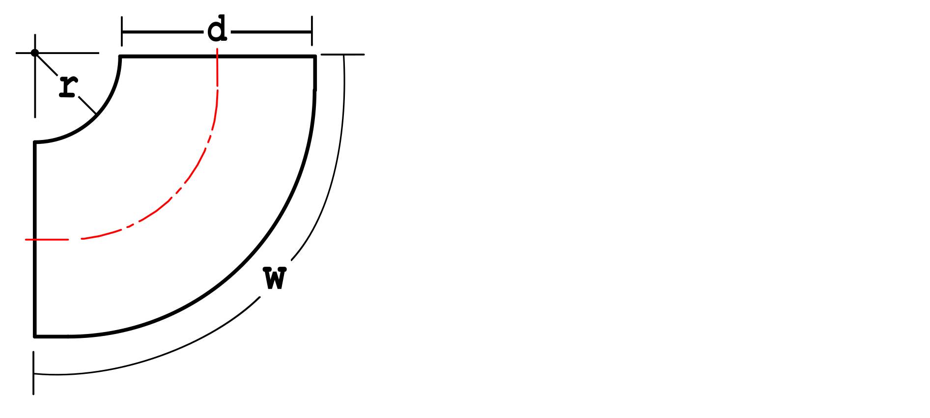
Where does Revit parametrics show its strengths? Well, it makes sense whenever it is possible to describe an object geometry based on a few parameters. For example bends are relatively easy to parameterize, since they are simple geometric bodies that can be modelled using fewer degrees of freedom. Bends are also components for which the final dimension is often not yet clear at the time of modeling, so some flexibility would initially be desirable.
In the simplest case a bend has a diameter, an inner radius and an angle. Based on these three specifications a simple parameterized bend can already be created. Now, additional parameters can be added as desired, which allow for example to parameterize connecting pieces or flange connections in shape and visibility. A simple fitting quickly becomes a universal model. Methods such as ETIM Modeling Classes or Revit Fabrication use the similarities of the shape for individual components in order to describe a sufficiently detailed geometry for design purposes based on on template objects by defining a few dimensions and angles.
Limits of parametrics
Parametrics can also be diverted from its intended purpose. This will quickly cause trouble in larger models, because bad parametrics slow down model performance. In most cases, such expensive parametrics are encountered where a series of products shall be represented within one family, but the product variants differ geometrically to such an extent, that no common parametric shape description can be found. In this case, you often meet one of the following two patterns.
Jack of all trades
First of all, there is the kind of family where desperate attempts are made to create the necessary degrees of freedom on the basis of countless parameters. These families, if they fulfill their purpose, are not problematic at first. However, when migrating to newer Revit versions, one observes conversion problems in some cases if too complex parametrics were used. Also, each parametric dependency generates small computational efforts when Revit has to regenerate the corresponding model sections. These small contributions can add up to a too complex mesh of dependencies in large projects.
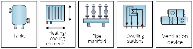
If parameterization is too complex for a component type, it may be worthwhile to look for family configurators that can generate a tailor-made family based on fewer user specifications. In the LINEAR world, such configurators are offered for tanks, air handling units or manifolds for example. The resulting families are slim, limited to the essentials and can be created or modified with a comfortable user interface.
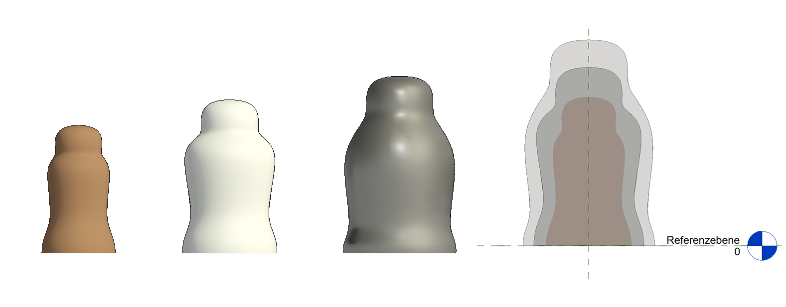
The matryoshka
Occasionally, we encounter a different pattern in practice, which we would like to call the "Matryoshka" family for the sake of illustration. In this modeling technique, the user is led to believe that there is a parametric product family. But in fact, the geometry of the represented products is kept redundant in all its forms. The geometry of a specific type is now controlled by a set of visibility parameters, which ensures that only the desired geometry is displayed and all others are hidden. This also works, but here the models may be inflated by data that is never used. Also, unlike multiple static families, cleaning up unused types has no chance of relieving the model in a "Matryoshka" family, since only the type definitions (i.e., the set of necessary yes/no parameters) can be removed, but not the redundantly held geometry.
Conclusion
Component families in Revit may, but do not necessarily have to be parametric. Parametrics is important and convenient to exploit similarity effects or to allow some flexibility in the design phase. As soon as manufacturer specific components are considered, i.e. the degree of geometric development is increased, it is advantageous to use families that either describe the one specific component or can be brought into the required shape via a clear set of parameters.
Myth 2: Dwg files in families must be avoided
Some modeling guidelines recommend that you only use families that are native to Revit, preferably those you created yourself. Embedding of DWG blocks is almost frowned upon. Especially manufacturer families are often deemed to be hopelessly obsolete and contain errors. However, the purist approach of generating each family itself is usually discarded after some time. At the latest when it turns out that your designers are also only human after all, the generation of families massively ties up resources and in the end you still do quite well with the available content from trustworthy sources, even if a part of the available families cannot meet the claim to be free from DWG files.
About the performance of embedded DWG files
Embedded DWG files suffer essentially from the fact, that they are associated with one of the greatest deadly sins among Revit users: excessive use of embedded DWG drawings in Revit projects. It even gets worse if you "explode" these CAD models into individual objects. The ability to use DWG drawings as a "background layer" is undoubtedly an important building block for the transition from AutoCAD to Revit, e.g. in redevelopment projects. If the drawings are not linked but embedded and then not removed from the model views, performance is likely to suffer. When asked what problems there are with embedded DWG files in families, performance and memory requirements are often cited as arguments. But do DWG files in Revit families share these unsightly characteristics at all, which are rightly attributed to them at project level?
First some basics: Revit families carry a certain amount of data. The minimum size of empty family files is about 300-400 KB. The decisive factor now is the additional amount of data required to model the actual component and the effort required to display it. With a few exceptions, RFA files should never have to exceed the size of one megabyte. Due to the family-instance principle in Revit, however, the principle "families are expensive, instances are cheap" fortunately applies to the pure file size, which is why the file size of the project results as a mixed calculation of families and their instances. Even here, DWG families are no exception, as we would like to demonstrate in the following with easily comprehensible examples.
Many identical elements
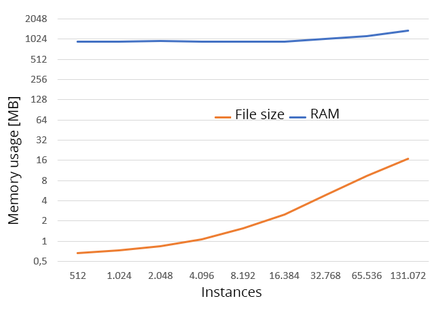
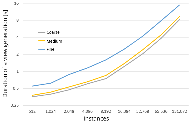
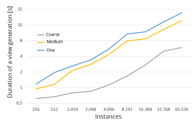
The first experiment is as follows: In an otherwise empty Revit project, we successively copy many instances of a single DWG family (here a FKU90 fire damper from the Wildeboer catalog 06/2021) and log the required hard disk space with each doubling step, the required memory after opening the project as well as the time, that a view creation (3D without cutting area with hidden lines) requires in the detail levels coarse, medium and fine.
While the process of initially adding the family enlarges the project by about 140 kB, each additional instance in the project file is added with about 120 bytes, whereas it is processed with around 3 kB at runtime. This footprint naturally increases with each instance parameter that is created and filled, so that for real projects a slightly higher storage load per instance must be calculated. In terms of performance, the effort involved in generating a view develops asymptotically linear with the number of elements to be represented, which is expected. Now this constructive example is by no means representative for a real project. However, with this simple experiment it can still be shown impressively, that many instances of individual DWG families do not show any notable differences in resource utilization.
Many different elements
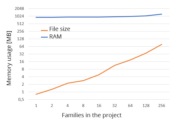
Now that there’s proof that it's not the number of elements but the number of families behind them, that affects the project size, let's take a second look at how memory usage changes depending on the number of individual DWG families in the project. With the LINEAR CAD browser we therefore add 256 randomly selected families from different manufacturers and product groups into an empty Revit project and log the storage loads.
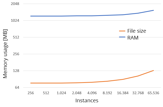
It can be observed that the reserved main memory of the Revit process remains largely unchanged. Only from 64 different families or more in the project a slight increase occurs. As expected, the project size increases linearly with the number of families in the project, with the average memory requirement in the project being about 300 KB per family. The required memory, on the other hand, can be estimated at an average of about 1.2 MB per family in use. Most families are not used only once in the project. Therefore, we extend this experiment by successively doubling the 256 families as before and again observing the memory and the required processing capacity for view creation.
Even in this example, which is much closer to real projects in terms of structure, no performance disadvantage of the DWG families can be determined. The size of the model depends substantially on the number of elements and the contained information density, which makes it difficult to give general estimates. However, with an average number of repetitions of just under 75 KB on the storage, the average required capacity per instance is already significantly lower than usual rules of thumb, according to which the project size should not exceed about 100 KB per component. Not to mention that, in addition to the product families, many lightweight system elements for pipes, etc. are used. There is still enough space for additional alphanumeric information on the elements.
Are there perhaps also good reasons to embed DWG files?
It is undisputed that DWG files are not a good basis if you want to model a parametric Revit family. However, there are also parametric source formats such as VDI 3805, that usually don’t allow for mapping to those of Revit and for which you therefore must generate individual families purely as a matter of principle to avoid the "Matryoshka effect". From the point of view of software development, it is only advantageous to provide an output format since one code for everything can be more easily maintained and expanded. This justification, however, still seems to be an inadmissible abbreviation chosen out of pure convenience.
A more convincing reason for sticking to the DWG embedding is, that Revit rejects the generation of geometric bodies with edge lengths below 1/32 inch (about 0.78 mm). This can usually not be solved automatically and can therefore lead to serious display errors. If a VDI 3805 model contains an edge with a length below this threshold - modelled intentionally or unintentionally - the resulting geometry cannot be generated as a Revit native family without errors. However, the transformation from VDI 3805 to DWG almost always works smoothly. Surprisingly, the geometries in DWG imports are usually stored more efficiently than when converted to Revit native geometries using the resolution feature in the family editor. Random samples showed that this effect can amount to up to 30% of the total size, minus the overhead of an empty family, thus resulting in an increase of about 100% in individual cases.
Conclusion DWG myth
The statement that embedded DWG files in families lead to problems cannot be backed up by facts. It is true that there are families based on far too detailed component drawings on various websites, which are not only memory-intensive, but also require unnecessary computing time in their handling.
In this case it is not the included DWG file that is the problem, but its content, which has not been optimized for use in the context of BIM. On the other hand, the detour via the DWG format currently offers the only stable way of generating VDI 3805-compliant geometries in Revit, which makes this the only reliable method if VDI manufacturer catalogs are to be converted into Revit families. Thus, we need to talk less about the data container of our component families and more about the quality of the actual content. This is a perfect transition to our last myth.
Myth 3: Only certified families are good families
When searching for suitable component families, Revit users often encounter the promise, that certain catalogs are certified while others are not. What is this all about? Can non-certified families still be trusted at all?
Well, it’s like buying groceries: If you distrust unknown sources, then in principle you are already doing something right. If a family originates from an online repository, then you alone are responsible for quality assurance. If, on the other hand, a component manufacturer offers official product catalogues, it is important that the manufacturer also assumes the final quality assurance and approves the component catalog for use in the software environments to be supported. But it does not require a certificate, such a thing should be a matter of course. No yogurt manufacturer would feel the need of writing "guaranteed edible" on their products.
Pure conformity certificates, which are issued by a single software manufacturer, are therefore to be evaluated at best as a marketing joke - at worst as documentation of loss of control. If you look at the necessary criteria for such a certificate, then often only the promise remains, that the respective content has classification keys and attributes for certain application programs. What sounds positive ultimately means, that the respective software does not offer an easy way to deal with unknown content for users, much less that it can map proprietary standards to internal specifications. The statement "Contains identifiers for software XYZ" can be read as “Software XYZ does not provide a classification mechanism”. Likewise, "Possesses attributes for calculation programs of company XYZ" simply translates to “We determine your company standards, not you". Therefore, when you read glossy brochures that offer certified component catalogues, always ask yourself whether this offers added value for you at all, or whether an individual manufacturer issues certificates according to homemade limitations.
Whether a seal of approval for Revit families is worth anything at all depends on the objectivity of the underlying criteria and their transparent documentation. Objectively measurable criteria here would be e.g. resulting data variables, the parametric complexity and the number of facets required for a three-dimensional representation in the preferred level of detail. Also, a good family should not unnecessarily work with provision of voids as well as - as far as possible - offer a simplified geometric representation where unessential details are not explicitly modeled. But even such objectively measurable quantities unfortunately say very little on their own. For example, some families, such as pipe accessories, already require certain details in initial design phase so that the function of the component can be recognized in the representation. Others can be exchanged practically without significant losses for most applications with a lightweight cuboid with connectors. If you want to perform a quality check for families in use, you cannot detach them from the overall context and have to stick to the evaluation in the constant alignment of costs and benefits for the overall project.
What should you do?
Establishing suitable quality features for Revit families and the development of integrated testing mechanisms based on them is an exciting question to which the author has to the best of his knowledge not yet given a final answer. Based on many years of experience, we can give you the following advice:
- Question blanket statements in guidelines. Revit has evolved over the last 10 years, publicly available guidelines often have not. Not everything that might have had its reason is still relevant for current versions.
- Clean up your model regularly and optimize only after you have measured. There is no special technical feature that makes DWG families particularly difficult to scale. Rather, behind almost every underperforming family there is poor modelling, independent of the geometry container.
- If the problem is not memory but the general performance, try to limit the work views to the area in which you want to work. Select an appropriate level of detail and display and disable the view of model components that are not relevant to your current task.
In conclusion, we can give you one urgent advice: Avoid using families from internet repositories if you don't trust yourself to put them through their paces. In the course of our research, we came across some interesting pieces, with a three-megabyte rectangular flange (consisting of just a cuboid and voids) deserving a special mention. The mentioned family, by the way, is Revit-native.
Dr. Christian Waluga