Parametric systems such as Autodesk Revit have several advantages in the general design phase (systems and integration planning) and in the construction design (execution design) that make their use in BIM processes worthwhile. For example, the concept of work sharing allows many actors to work concurrently in the same authoring model. Furthermore, the high degree of parametric modeling and the use of neutral parametric component families are advantageous when it comes to building and optimizing a MEP network.
However, if the level of detail is to be increased further after the construction design, for example, to derive documents for prefabrication or assembly, the boundary conditions change abruptly. From this point on, parametric geometries and creative collaboration become less relevant, while the importance of reliable product information and correct positioning and connection in the model increases. It is no longer sufficient that components are merely described in terms of shape, position, orientation, and connectivity. From this moment on, manufacturer-specific instantiation must also be carried out in careful diligence. Also the connection of the products to each other must be explicitly modeled if bills of materials and assembly plans are to be derived for the actual construction.
At this point at the latest, the usual Revit modeling, referred to in the following as Revit design, does not provide the desired level of comfort. Although it is possible, for example, to correctly place flange connectors with the help of a few tricks or suitable modeling tools, the effort involved is high. Furthermore, the intelligence inherent in Revit ensures that such components are marked as superfluous during network modification and are cleaned up accordingly. You realize pretty quickly that Revit design is not the right tool for the job from this point on.
To meet the challenge of detailed construction and assembly design, there are several approaches - in addition to the consistent use of Revit design techniques - that ultimately all amount to transforming the model into a more detailed model. In the following, we will highlight a common as well as our own and novel one.
Autodesk Fabrication
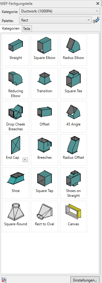
Autodesk Fabrication in Revit offers a way to use component models with given parametrics. In contrast to classic Revit families, the Autodesk Fabrication product family allows lightweight component catalogs to be captured with correct connection logic and metadata useful for subsequent process steps. Once captured, these part catalogs present themselves to the user like a manufacturer’s catalog, in which the scope is limited to components that can actually be ordered. Subsequent modification is prevented with administrative care, just like the addition of further components from unknown sources. For all the advantages offered by the approach, there are also disadvantages. On the one hand, when converting an existing Revit design model into a Fabrication model, any information about underlying system assignments is lost and must be managed by the model author in another way (e.g., through assignment of media per parameter or Fabrication configurations). On the other hand, not every company has the capacity to employ its own content creators for this use case.
Since the creation and daily maintenance of Fabrication content is time-consuming, hardly any manufacturers currently offer this service due to a lack of practical demand. Without content, however, there is no practical application, which closes this vicious circle. One exception is the ventilation sector, where individual production of ducts and molded parts is widespread anyway. With the help of a neutral Fabrication configuration, ventilation systems can be easily either rebuilt or semi-automatically converted on the basis of a Revit design.
Especially when model authors change between construction and assembly installation design, the question arises whether such networks can be recalculated for control purposes before fabrication and assembly. From version 23.1, LINEAR therefore offers the additional option of calculating Fabrication networks in detail with Analyse Ventilation for Revit.
LINEAR Design 3D
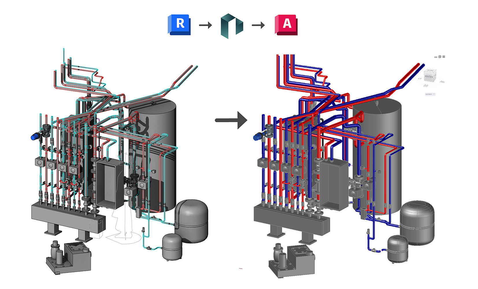
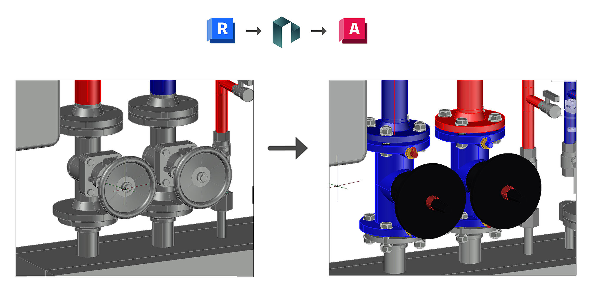
Our alternative approach tries to circumvent the difficulties mentioned above. It involves exporting a Revit design model to a handover container using an export step and then rebuilding it in LINEAR Design 3D for AutoCAD using manufacturer-specific pipe and duct classes. The advantage here is that there is no transfer of internal project organization. Thus, a LINEAR user is ultimately free to decide whether to provide the contractor with the entire project or only the design 3D container (.d3d) for the transition to AutoCAD-based solutions.
Meanwhile, the quality of the model transformation between Revit design and AutoCAD is comparable to the previously discussed transformation to Revit Fabrication. In the case of errors resulting from a limited product range compared to the Revit parametrics, the import mechanism in AutoCAD first tries to find suitable alternatives in the component catalogs. If this is not possible, the user is informed about this in the form of a report and can then view the problem areas manually.
After successful transfer to Design 3D, both sophisticated design tools and tested manufacturer content are available to you for further detailing. The architectural model can be linked by means of an IFC or DWG file as a reference for your design.
The advantage of this approach is that the original Revit model is retained in the given form and can be compared with the detailed version at any time for control purposes. By the way, this does not have to be done for the complete model: It is also quite conceivable to transfer only neuralgic points, such as equipment rooms, to a highly detailed model, while the rather boring model sections are available in a lower level of detail.
Conclusion
This article is intended to make it clear that there is no right or wrong way to choose a tool for modeling in BIM processes. The question that arises is rather that of the required modeling depth and the appropriate platform. We want to give our users the choice when it comes to detailing: If the advantages of continuing to work in Revit design outweigh the disadvantages despite limited comfort, we offer tools to support you in this task. If you prefer to create a fabrication model within Revit, then we have already taken the first step in the area of ventilation to check the system again by calculation after the detailing has been completed. If you need sophisticated design tools as well as manufacturer-approved content libraries and normative calculations in all disciplines already today, then our Design 3D solution supports you in the transfer from Revit design to LINEAR for AutoCAD. The underlying functionalities are already available to our software subscription customers at no additional cost.