Details about Pre-wall technology
Information about the dialog Pre-wall technology in 3D construction.
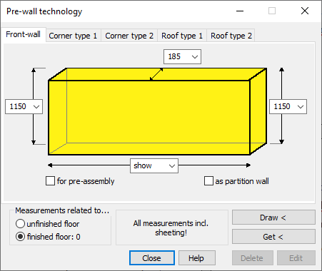
The Pre-wall technology dialog allows you to create installation walls for sanitary rooms as pre-wall or partition wall constructions for various installation situations.
You are here:
The individual tabs offer different design forms: A cuboid Front-wall, the triangular corner shape 1 for installation in a corner of the room, corner shape 2 for free positioning with planking on all sides and two roof shapes.
Front-wall tab
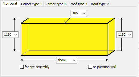
Dropdown lists for sizing the front-wall:
Constr. height - Sets the construction height(s) of the installation wall. Either select one of the suggested front-wall heights, enter a height yourself, specify that the front-wall should have room height (RH) or that you want to Show the height when placing the front-wall in the drawing.
Constr. depth - Sets the construction depth of the installation wall. Either select one of the suggested front-wall depths or enter a depth yourself.
Constr. length - Sets the construction length of the installation wall. Either select the suggested front-wall length 1000 mm, enter a length yourself, specify that the front-wall is as long as possible (max) or that you want to Show the length when placing the front-wall in the drawing. The maximum length depends on the length of the wall in front of which the installation wall is drawn. For front-walls that have already been drawn, the two Show new checkboxes are activated. Use Show new to redefine the end points of the front-wall in the drawing. After activating the checkbox(es), use the Change button to switch to the drawing and define the new end point(s) there.
All dimensions for the front-wall are inclusive of sheeting and tiles.
for pre-assembly/as partition wall
Specifies whether the installation wall is to be a front-wall suitable for pre-assembly or a free-standing partition wall construction clad on both sides. Front-walls suitable for pre-assembly are drawn with the required wall thickness.
Corner type 1 tab
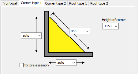
Corner type 1 is designed for corner installation.
Drop-down lists for dimensioning the corner type:
Set the dimensions for the corner shape. Either choose one of the suggested values, enter a value yourself, specify that part of the dimensions should be determined automatically (auto) or that you want to Show the dimensions when placing the corner wall in the drawing.
Height of corner wall
Defines the height of corner wall. Either choose one of the suggested corner wall heights, enter a height yourself, specify that the corner wall should have room height (RH) or that you want to Show the height when placing the corner wall in the drawing.
All dimensions for the front-wall are inclusive of sheeting and tiles.
for pre-assembly
Activated: A corner type with wall thicknesses suitable for pre-assembly is drawn.
Corner type 2 tab
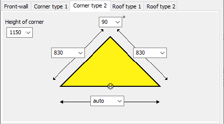
Corner type 2 is planked on all sides and can therefore be placed freely in the room.
Drop-down lists for dimensioning the corner type:
Set the dimensions for the corner shape. Either choose one of the suggested values, enter a value yourself, specify that part of the dimensions should be determined automatically (auto) or that you want to Show the dimensions when placing the corner wall in the drawing.
Height of corner wall
Defines the height of corner wall. Either choose one of the suggested corner wall heights, enter a height yourself, specify that the corner wall should have room height (RH) or that you want to Show the height when placing the corner wall in the drawing.
All dimensions for the front-wall are inclusive of sheeting and tiles.
Angle degree
Sets the degree of the upper angle. The degree of the two base angles result from the degree of the tip in combination with the selected length of the legs. Either choose one of the suggested values or enter one yourself.
Roof type 1 tab
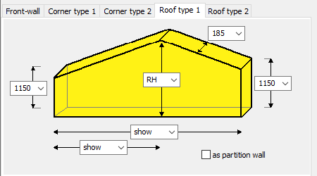
Roof shape 1 is intended for gable-top front-walls.
Drop-down lists for dimensioning the roof type:
Set the dimensions for the roof shape. Depending on the selected drop-down list, you can either choose one of the suggested values, enter your own value, specify that the room heights are used or that you want to Show the dimensions when placing the corner wall in the drawing. With max you have the option to specify that the maximum length is drawn in. The maximum length depends on the length of the wall in front of which the installation wall is drawn.
All dimensions for the front-wall are inclusive of sheeting and tiles.
as partition wall
Activated: A free-standing partition wall construction clad on both sides is drawn.
Roof type 2 tab
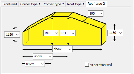
Roof shape 2 is intended for front-walls without gable-top.
Drop-down lists for dimensioning the roof type:
Set the dimensions for the roof shape. Depending on the selected drop-down list, you can either choose one of the suggested values, enter your own value, specify that the room heights are used or that you want to Show the dimensions when placing the corner wall in the drawing. With max you have the option to specify that the maximum length is drawn in. The maximum length depends on the length of the wall in front of which the installation wall is drawn.
All dimensions for the front-wall are inclusive of sheeting and tiles.
as partition wall
Activated: A free-standing partition wall construction clad on both sides is drawn.
Measurements related to...
Specifies whether the bottom edge of the front-wall is drawn on the Unfinished floor or on the Finished floor.
Draw </Get <
Draw <: Switches to the drawing to assign and draw the front-wall to a wall. The starting point of the front-wall is always the next wall end point related to the point you clicked when selecting the wall. If you have selected Show at front-wall length, you will be prompted to show the length in the drawing. If you have selected max or entered a fixed length, the front-wall will be drawn directly after the start point of the front-wall has been defined.
Before you draw in front-walls in 3D front-wall planning, you should switch to the isometric drawing view. This will make your work easier.
Get <: Allows you to select a front-wall in the drawing, for example, to make changes to it.
Delete/Edit
Delete: Enables the deletion of drawn pretexts. If necessary, you must first select the wall to be deleted in the drawing using the Get < command.
Edit: If you have made changes in the dialog of an already drawn front-wall, you can transfer them with Edit.