Details on Network Generator
Information about the Network generator dialog of the Rain drainage assistant.
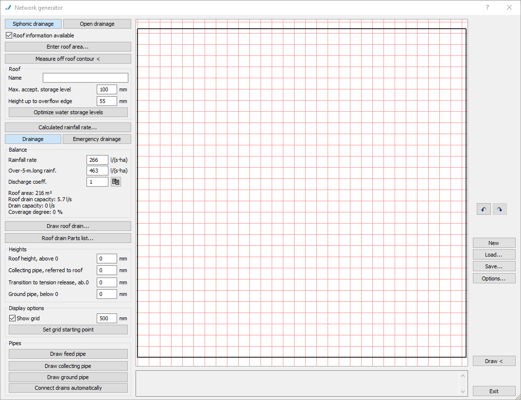
Use the network generator to create calculable roof drainage pipe networks and have them drawn automatically in 3D. You can generate siphonic or open drainage pipe networks. For both drainage types you can create and calculate pipe networks with or without roof. You can create and calculate roof drainage pipe networks with or without a roof. Without roof information, no roof balance sheets or area data is output in the calculation. In this case for each roof drain the volume flow rate is to be entered.
You are here:
Siphonic drainage/Open drainage
Defines the drainage type of the pipe network for roof drainage.
Roof information available
Activate the Option if the required information for the definition of the roof is available.
Activated: The input of the roof information is activated. You can specify the dimensions of rectangular flat roofs using the Enter roof area button or pick up the roof contour from the drawing.
Deactivated: The input of the roof information is activated. The drawing area can be defined using the Enter drawing area... button. Without roof information, no roof balances or area data are output in the calculation, and the drain capacity is given for each drain. The options Optimize water storage level and Calculated rainfall rate ... as well as the fields in the Balance section are not available.
Enter roof area.../Enter drawing area...
Opens the Roof area dialog for calculating the areas of rectangular flat roofs by entering the roof dimensions. The roof area is then displayed in the drawing area of the network generator.
Measure off roof contour <
If you have inserted the floor plan of the building as a base, use the Measure off roof contour < command to define the corner points of the roof contour in the drawing or using the base. Then the roof area is shown in the drawing area of the network generator and the checkbox Roof information available is activated.
Roof
The area is activated only if the Roof information available checkbox is selected.
Name
Choose an individual name for the roof and determine the name here.
Max. accept. storage level
Defines the statically maximum acceptable storage height of the roof. The value is transferred to the component dialog of the roof area in LINEAR Analyse Waste Water.
Height up to overflow edge
Defines the height up to overflow edge of the roof. The value is transferred to the component dialog of the roof area in LINEAR Analyse Waste Water.
Optimize water storage levels: After drawing in or modifying roof drains, you can use this command to have the values for the Maximum acceptable stowage height and the Height up to overflow edge optimized. The command is activated only if the Roof command available checkbox is selected.
Calculated rainfall rate
Calculated rainfall rate...
Opens the Rainfall rate dialog, allowing you to accept the corresponding rainfall rate data by specifying the project location, and to adjust it if necessary. The command is activated only if the Roof command available checkbox is selected.
Drainage/Emergency drainage
Specifies whether a waste water pipe network or an emergency drainage pipe network should be created.
Balance
The area is activated only if the Roof information available checkbox is selected.
Rainfall rate
Specifies the calculated rainfall rate value of the selected project location. You can manually adjust the value as needed.
Over-5-minutes-long rainfall
Specifies the calculated Over-five-minute-long rainfall rate value of the selected project location. You can manually adjust the value as needed.
Discharge coefficient.
At first, the discharge coefficient is suggested as most unfavorable value 1.
Discharge coefficient 
Opens the Discharge coefficient dialog, allowing you to specify, among other things, other roof surfaces with the associated discharge coefficients.
Roof area/Roof drain capacity/Drain capacity/Coverage degree
Summary of the calculated values.
Draw roof drain
Draw roof drain...
Opens the 3D roof drain (...) dialog allowing you to define the desired roof drain and then draw it in.
Roof drain Parts list
Roof drain Parts list...
Opens the parts list of the drawn roof drains.
Heights
Allows you to define, depending on the selected drainage type, the required heights for the creation and calculation of the waste water pipe network. The height of the Collective pipe, in referred to roof does not have to be entered negative. It is automatically created under the roof area. You can subsequently adjust the heights and then have the pipe network redrawn. This does not require repositioning of the pipes in the network generator.
Display options
Show grid
Activated: In the drawing area of the main dialog you will see a red grid to help you draw. You can define the size of the grid yourself.
Set grid starting point
This command allows you to set a grid snap in the drawing area.
Pipes
Draw feed pipe
Starts the drawing command for feed pipes. It may happen that not all drains are connected automatically. In these cases, use the Draw feed pipe command to draw the feed pipe manually.
Draw collecting pipe
Starts the drawing command for collecting pipes.
Draw ground pipe/Draw draw-off pipe
Starts the drawing command for ground or draw-off pipes. Depending on whether you have set the Drainage (Draw ground pipe) or Emergency drainage (Draw draw-off pipe) option, one of these two options will be displayed. At the transition from collection pipe to ground pipe the down pipe will automatically be generated subsequently. At the end of the ground pipe a network start symbol is inserted automatically.
Connect drains automatically
Allows to automatically connect your drains.
Further commands
 /
/
The buttons allow you to undo commands and restore undone commands.
New
Allows you to create a new pipe network You will be asked by the program whether the old drainage pipe network is really supposed to be discarded, so that you will have the opportunity to save your settings.
Load...
Allows loading of previously saved drainage networks (*.drainage file).
Save...
Allows saving drainage networks as *. drainage file.
Options...
Opens the Options dialog allowing you to specify additional presettings to connect the drains and to draw cleaning openings.
Draw <
Starts the drawing command to draw the created drainage pipe network in three dimensions. After drawing in, let the network be calculated.
Close
Closes the dialog.