Details on 3D Sections/views
For information on the 3D Sections/views command, see Display.
This command allows you to define, name and save multiple vertical sections in a 3D drawing. First, section lines are drawn at a certain height, which can then be used to create viewports with these section views at different scales in the layout.
You are here:
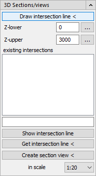
Draw intersection line <
Z-lower / Z-upper: First set the height at which the bottom and top edges of the section should be created in the Z-upper and Z-lower fields. Enter the value of the absolute height in mm or click the button  to open the table of storeys.
existing intersections: List of generated intersection lines.
Show intersection line
The Show intersection line command automatically zooms in on the desired section. This makes it easier to find the sections in large, complex drawings. Select the desired section in the existing intersections window and on the Show intersection line button.
Get intersection line <
With the Get intersection line command, you can easily find the intersection again in the list of existing intersections. Click a section line in your drawing. The cut will be marked in the list.
Create section view <
Then click Create Create section view <. The cut is now attached to the cursor and can be inserted into the layout. It consists of a group of viewports whose display settings can be set via the Visual styles. When creating a section view, a separate viewport is created.
in scale
Use the drop-down list to set the scale for the section view you want to create.