One thing is, however, already clear. The component models used, from the central ventilation unit to the regulating valve, have to be designed more flexibly than they have been up to now. We would like to allow the planners, in other words the “consumers” of design software and component models, to have a harmonious model for each design phase without manual corrections to individual components over the long term.
Above all, a consensus has to be found on how component models should be structured in order to meet these requirements. With this article, we would like to throw some light on how this may look.
Basics for developing the building model
In very early pre-design phases, the MEP contributes mainly with supply concepts and the space requirements needed for these. Space requirement is ideally modeled in the form of provisional placeholder solids (“Provision for Space”) in the building. This initially involves the placement of equipment rooms and the pipeline routing. Component models do not yet play any role here.
These are only used later in the pre-design, initially for components with relevant space requirements. For these components, the planner needs provisions in order to be able to make a more concrete statement about the space required, for example in the equipment rooms. Additional details are also rather obstructive; because you are committed with this thus have to pay more attention to it than is strictly necessary.
In the outline planning, at the latest, all components are required with information about their function and connection position. In this case, it might make sense to use manufacturer-specific components wherever the use of a specific product is already relatively certain and a later re-design is rather unlikely.
For public building projects, the planner still has to be able to provide a neutral or neutralized model for tender. At the same time, however, it becomes more important to be as concrete as possible starting with the implementation planning and, at the latest, in the construction design. Non-specific, neutral components show insufficient accuracy in many areas. If a neutral component was used in the earlier phases, it is now replaced by a specific component. It is obviously easier if the component is specifically modeled from the beginning, but is able to hide the specific features up to the point where they are required.
Structure of the component model
Initially, we distinguish simply between neutral and manufacturer-specific components. Neutral components should be structured very flexibly as a Revit family, so that they can approach as close as possible to reality in terms of space requirement and, where relevant, operating side. However, no neutralized variants of families, which form manufacturer-specific components, are needed. The advantage of a neutral family - the flexibility and the fact that you do not yet have to commit yourself exactly - would thus be given up.
Manufacturer-specific components require more nuances in detail, as the planner initially only wants to map the space requirements or concept, and later illustrate the functionality, only becoming very specific at the end. Everything with a single family. In addition, manufacturers would like to have their products identifiable as such in model planning - and quite understandably visually as well.
This important aspect should not be ignored. Manufacturer-specific products are essential at the latest for construction design or even pre-fabrication. The effort to capture the models and data for this is huge and therefore expensive. If we force manufacturers to reproduce their models with as little detail as possible, they often lose the recognition value and the manufacturers eventually lose the desire to continue the effort. The aim therefore has to be to build the models in such a way that the manufacturer is marketing department is satisfied and planners are - nevertheless - happy to use these components in their building models.
What is important to the planner here? The planner expects good component models to be dimensionally accurate, especially in the connections, to perform well - i.e. the components do not require too much of the computer’s resources either in terms of memory or graphics - and he also expects a completely neutral representation of the component up to the tender stage. However, the component should be able to “come out “then.
How is this balancing act to be achieved?
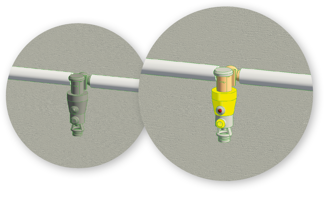
The art is to provide the models only with the details necessary for unambiguous recognition and then make them (dis-)switchable down to neutrality. First, the details include the coloring. The mapping of the material colors is often the recognition factor par excellence and this costs no performance at all (see Figure 1). Followed by the special shaping and - depending on whether these are needed - the logos of the manufacturers or of the product series. It is important to ensure that these details do not strain the performance too much. Chamfers, beads, curves, threads, screws, grids, etc. generally contribute little to recognition and should only be hinted at or omitted altogether, because they lead to massive performance losses.
In order to still be able to represent these components in a completely neutral way, the modeled details that “reveal” the product, - especially logos - should be separated from the general shaping. In Revit, these can then be (de)activated separately.
Composition of the models
Component families usually consist of several model parts, which are either shown alternatively (component body sometimes very simple and sometimes detailed), or are displayed in a supplementary manner, such as a product logo can supplement the detailed component body, or the operating space can also be additionally shown or hidden.
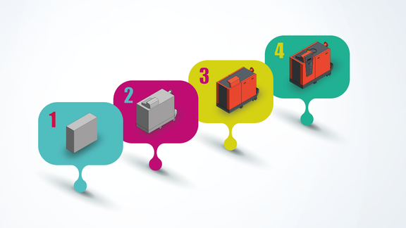
Since the alternative displays are mainly different levels of detail, it makes sense to tie them to Revit’s level of detail switching. Revit does allow three levels of detail to be selected “out of the box” (coarse/medium/fine). In the piping trades, however, only two of them are actually available, since “REVIT FAMILIES” display pipelines, both “ coarse “ and “ medium “ only as one line. You can choose between a “single-line “and a corporeal representation - that is it. Fortunately, this can be remedied by selectively increasing the display level for the affected categories. We do this automatically in our Desktop solution, but it can also be set manually in the view settings.
In the end, however, only three display variants remain. This is not quite enough to be able to map the necessary variants. The sub-category system creates the remedy in this case. If model parts are assigned to a sub-category, these parts can become visible or invisible by switching the category on and off. The important point for this is that it can occur view-dependently. You can, for example, create a view for the product-neutral tender, while in another example renderings with detailed representation are already made. Component categories that are completely missing in Revit can also be replaced by sub-categories. We were missing, for example, a category for the fixation trade. For this purpose, we see a sub-category “Fixation” in the “General Model” category.
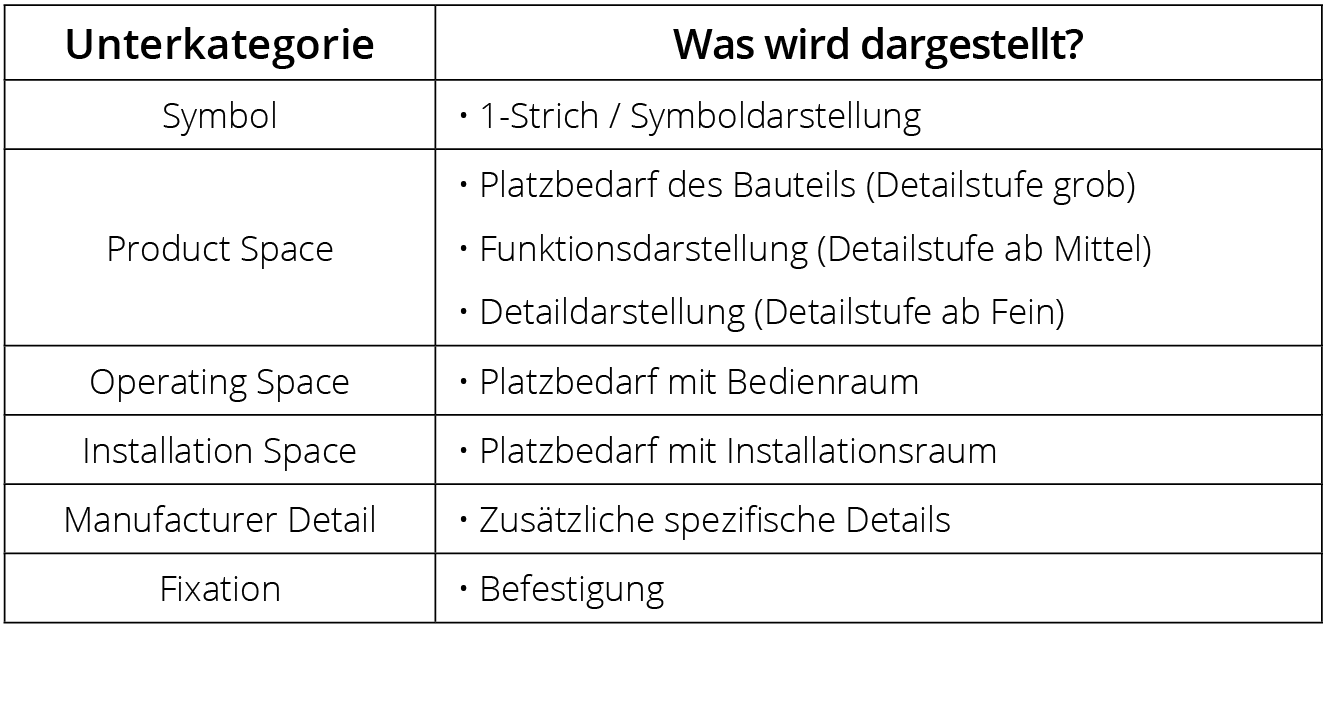
The challenge at this point is to build consensus for the necessary sub-categories and their naming. If there is no consensus here, the user has to deal with an unmanageable chaos. To avoid this, we are publishing our presentation of the necessary sub-categories in Table 1. We have based our choice of names on those commonly used in VDI 3805.
You should make sure that the levels of detail used in the families are compatible with each other. There is no sense, for example, in leaving the “Fine” detail level blank in neutral families, just because you don’t have a separate representation for it. Another example: If you do not have a symbol in the “Rough” level of detail, but only a simple physical display, you should not use a sub-category for this, because otherwise the component will be completely invisible if the user actually wishes to see symbols.

Single line or symbol display
Symbol display can be both a means to display concepts at very early stages, but can also be supplemental information on the physical component. This is often used in ventilation, for example, where many components are simple boxes when seen from the outside. This function can be displayed very well by means of a symbol. In both cases, it should be possible to switch the display on and off.
The simplest physical display
Components have to be divided into two classes here:
1. Components that are installed in pipes or ducts
In early phases, these components are not even installed. However, as soon as you are installed, you should also be able to recognize the function of the component. Therefore, a simple but meaningful display is already necessary for the rough display. A placeholder in the form of a bounding box or a bounding cylinder does not make sense.
2. Components that will be placed freely
(generators, consumers) the more space a component requires, the more sense it makes to integrate it into the planning at a very early stage. As early as possible, you might wish to make a statement about the space required, but not yet about the specific component. Therefore, a placeholder is offered at this point (in the simplest case, in the form of a bounding box or a bounding cylinder).

The medium physical display
In this case, much the same applies for all components:
- The model is intended to display the function of the component as far as possible. Thus, for example, display the control elements and the operating side.
- The model is intended to reproduce the space required for the component as far as possible.
- The model should contain as few details as possible to keep the render performance high for the daily work.
Neutral components with a variable space demand should be of a configurable size. Manufacturer’s components “may “give hints about the product (rough shaping), e.g. to show the space requirement more precisely, but this should be as discreet to not lead to difficulties in public tenders.
The detailed physical display
Once again, a sub-division into two classes here:
1. Manufacturers’ components
The model may now be clearly identifiable as a product. Characteristic details that do not make any statement about the function (such as logos) should - used sparingly - be placed in the “Manufacturer Details” sub-category. Fixation details should be placed in the “Fixation” sub-category.
2. Neutral components
The medium level model can be used.
Materials / Colors
Colors that are typical for a brand name or product range should of course be available, but also neutralizable. This is achieved by means of materials that share different visual properties for shaded and realistic displays. This allows a realistic display in product colors, but at the same time a view-wise switch back to the neutral color scheme.
How do you actually get there?
The suggestions described here have been considered from the end; therefore, they are only the desired result. There are many ways of getting to this result. The most obvious is manual, native modeling of the families with the Revit family’s editor. This is offered mainly if a lot of flexibility in the family is required. Thus, mainly for neutral families which, for example, are intended to “grow” with the pipe dimension.
Another way is the provision of VDI 3805 catalogs, which is particularly suitable for manufacturer-specific components. If a few rules are observed here, e.g. separating the body model and logo already in the data set, it is the best way for many component types. In combination with a piece of software - for example the liNear CAD browser - the products, product options and accessories can be offered very clearly in catalog form and then output directly, on request, as Revit families in the quality described above. The demand from the planning world to maintain high quality, well thought out Revit families is getting louder and louder. Rightly so. The time of overloaded families is over as well as the frantic attempt to parameterize every family. Customized detailing and flexibility are as much in demand as comprehensive standardized use. There are not many agreements to be made at all, but it is even more important that they are made.
Join us, have your products modeled according to this guideline and give us your feedback. Preferably, with constructive criticism or amendments.